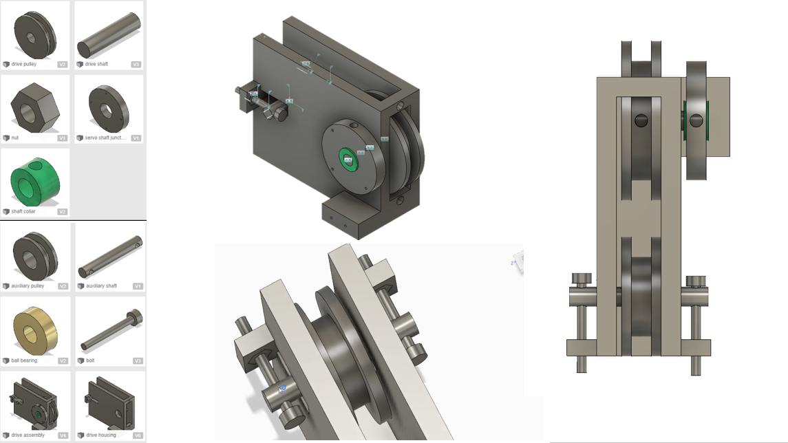
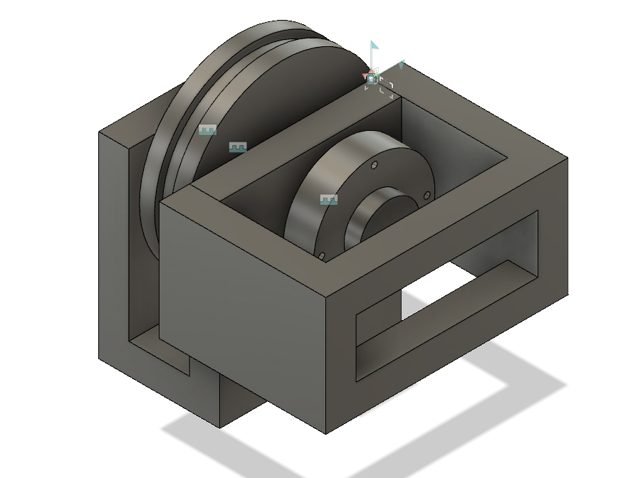
See previous posts for earlier in the process. After some prototyping, I addressed the tension and strength issues present by beefing up the design and adding a secondary tensioning pulley. I started with this design for how all the drives would fit in the housing.
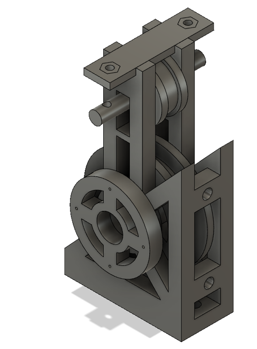
It quickly became evident that it was going to be terrible to route all the cables, so I went with a more modular and spaced out design, and changed the drive assembly to be vertical to more efficiently use the available footprint. this is the design in Prototype 4
At this point I realized that this thing was going to be way to heavy. The legs I were using could support about a pound apiece, but each drive assembly was half a pound, and the housing itself was going to be another 6+ pounds. I cut as much weight from the drive design as possible, but it was still too heavy
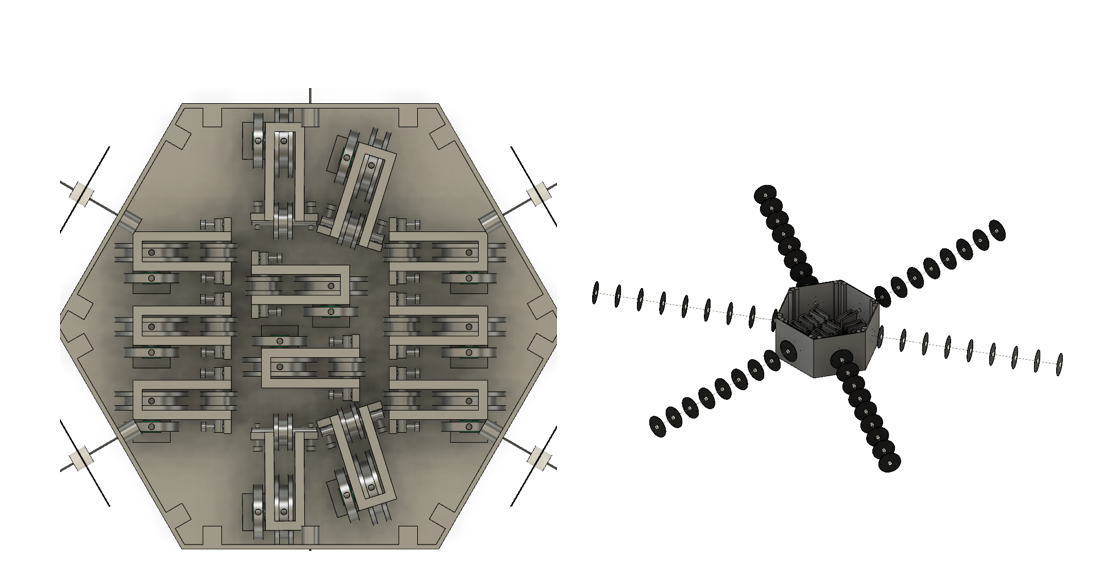
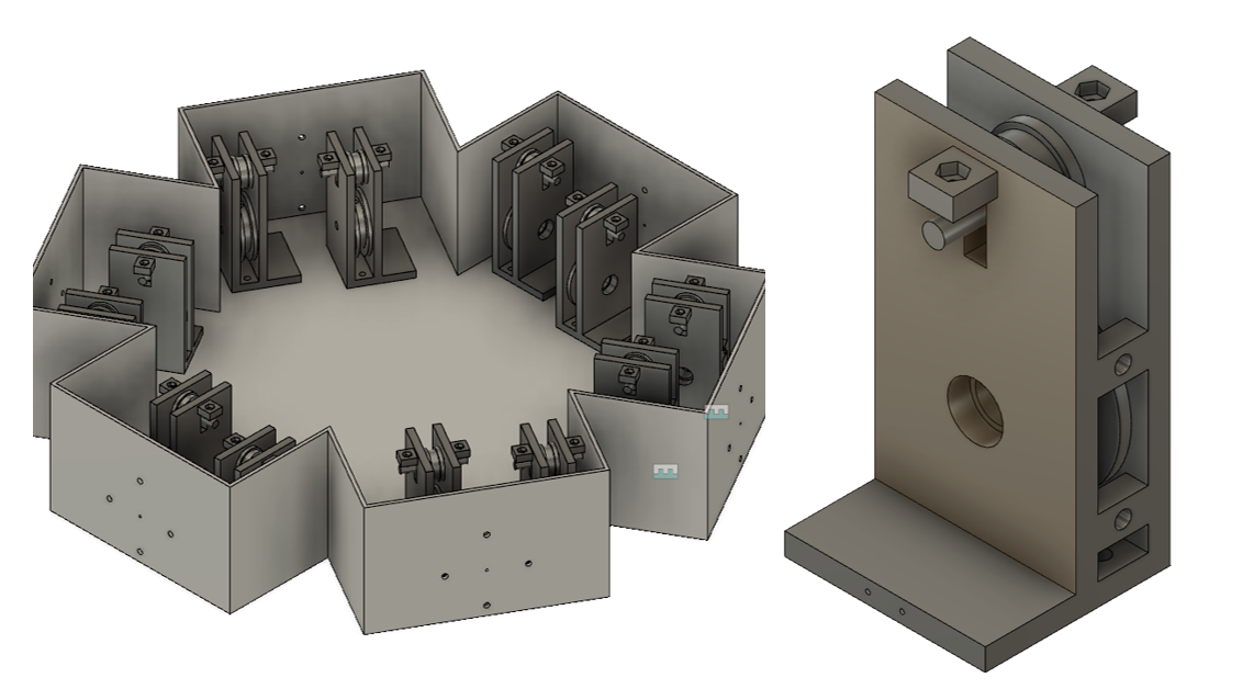
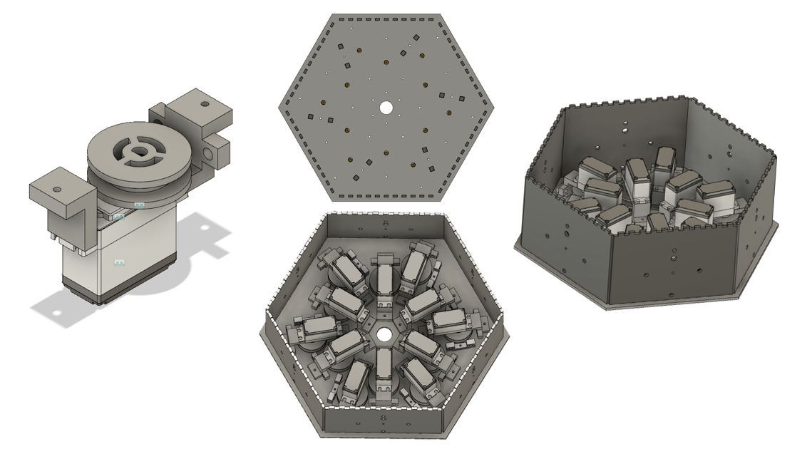
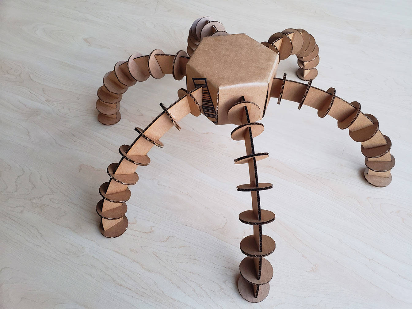
It was then back to the drawing board. I decided to use the body as structural support as much as possible to add as little additional material as I could with the drive mounts. I moved back to a hexagonal prism design to save material on the housing, and made one little bracket for each side with the pulley mounted directly to the servo and the encoders mounted to the body.
Final Fabrication
Time Lapse
Parts List
1/32" delrin sheet
1/8" black acrylic sheet
1/8" white acrylic sheet
1/4" white acrylic sheet
Bicycle brake cable
6x 2' long 0.098" diameter carbon fiber rods
50 LED strand of WS2811 LEDs cut into 6 pieces 8 LEDs long
The arms were made of carbon fiber rods with 8 delrin discs running the length. Each disc had a 1/4"acrylic washer in the center to aleviate stress between the discs and the carbon fiber. The rod fits into a hole in the side of the body, and 4 brake cables route the tensioning wire from the servos to the arms.
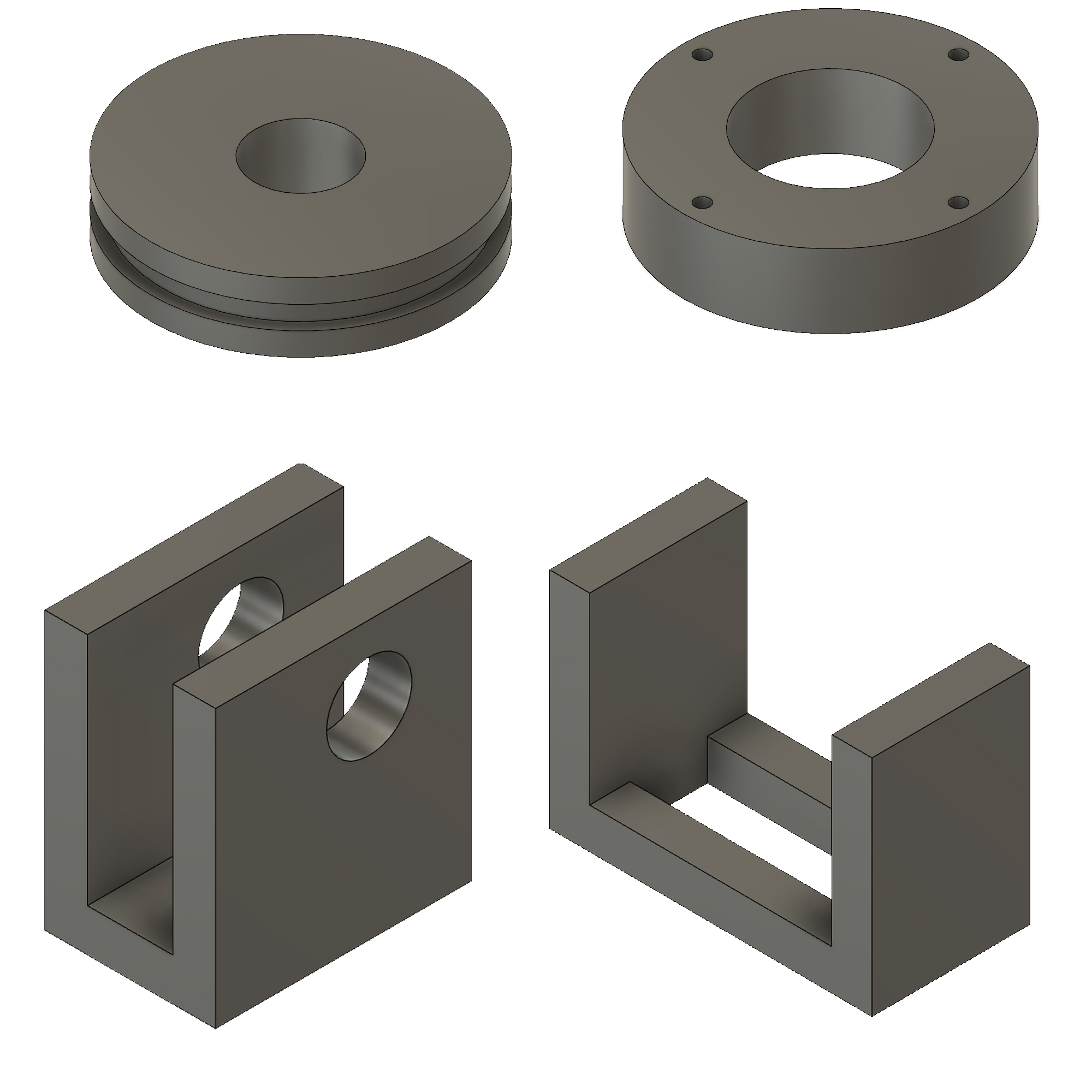
The servo mounts cosisted of two brackets on either side of the servo. Because of the way they are mounted in the body, one has the brake cables in front of the servo, attached directly to the mount, while the other has the brake cables attached to the side, with a separated bracket for the brake cable. The pulleys consist of 3 layers cemented together.
The body is a hexagonal prism fit together with finger joints, and the bottom plate is the central piece to which all of the hardware is mounted.
Electronics/Software
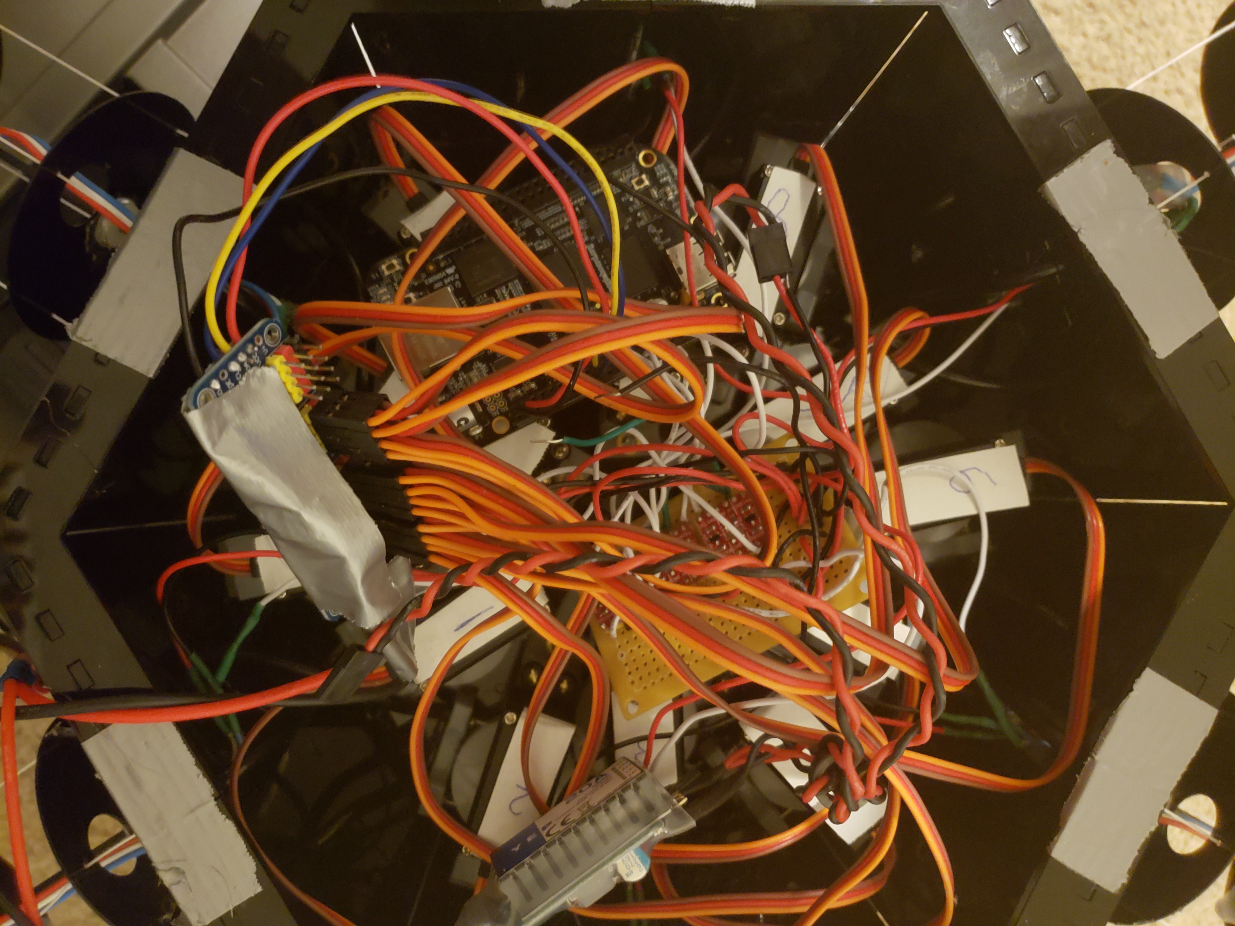
The wiring itself isn't too complicated, there are just a lot of wires due to the number of components. The battery powers the SBEC and V+ on the servo driver board, and the lights and the Beaglebone Black get 5V from the SBEC. The servo driver communicates with the BBB using I2C, so VCC, GND, SDA, and SCL are connected to the pins with those names on each board. I chose the BBB because it has two onboard PRUs (programmable realtime unit, essentially a small realtime microcontroller that runs at 200MHz), and while the main processor isn't realtime and therefore doesn't have the precise timing needed to interface with the LEDs, the PRUs do. The PRU on the BBB can only access specific pins, so the LEDs are connected to pins P9_31, P9_29, P9_30, P9_28, P9_42, and P9_27. Between each of these pins and their LEDs is one of the logic level converters, with TX0 connected to the LED strands and TX1 connected to the BBB. HV is connected to 5V and LV to 3.3V, and GND is connected to ground. The servos are all plugged into the servo driver board.
I used a slightly modified version of neo4.c from the PRU Cookbook to run on the PRU, which takes the information written to it from Linux on the main processor and writes it out to the LEDs. The change I made was to allow it to write to 6 strands instead of 1.
// Use rpmsg to control the NeoPixels via /dev/rpmsg_pru30
#include <stdint.h>
#include <stdio.h>
#include <stdlib.h> // atoi
#include <string.h>
#include <pru_cfg.h>
#include <pru_intc.h>
#include <rsc_types.h>
#include <pru_rpmsg.h>
#include "resource_table_0.h"
volatile register uint32_t __R30;
volatile register uint32_t __R31;
/* Host-0 Interrupt sets bit 30 in register R31 */
#define HOST_INT ((uint32_t) 1 << 30)
/* The PRU-ICSS system events used for RPMsg are defined in the Linux device tree
* PRU0 uses system event 16 (To ARM) and 17 (From ARM)
* PRU1 uses system event 18 (To ARM) and 19 (From ARM)
*/
#define TO_ARM_HOST 16
#define FROM_ARM_HOST 17
/*
* Using the name 'rpmsg-pru' will probe the rpmsg_pru driver found
* at linux-x.y.z/drivers/rpmsg/rpmsg_pru.c
*/
#define CHAN_NAME "rpmsg-pru"
#define CHAN_DESC "Channel 30"
#define CHAN_PORT 30
/*
* Used to make sure the Linux drivers are ready for RPMsg communication
* Found at linux-x.y.z/include/uapi/linux/virtio_config.h
*/
#define VIRTIO_CONFIG_S_DRIVER_OK 4
char payload[RPMSG_BUF_SIZE];
#define STR_LEN 48
#define oneCyclesOn 700/5 // Stay on for 700ns
#define oneCyclesOff 600/5
#define zeroCyclesOn 350/5
#define zeroCyclesOff 800/5
#define resetCycles 51000/5 // Must be at least 50u, use 51u
#define out 1 // Bit number to output on
#define SPEED 20000000/5 // Time to wait between updates
uint32_t color[STR_LEN]; // green, red, blue
/*
* main.c
*/
void main(void)
{
struct pru_rpmsg_transport transport;
uint16_t src, dst, len;
volatile uint8_t *status;
uint8_t r, g, b;
int i, j, out_ind;
// Set everything to background
for(i=0; i<STR_LEN; i++) {
color[i] = 0x010000;
}
/* Allow OCP master port access by the PRU so the PRU can read external memories */
CT_CFG.SYSCFG_bit.STANDBY_INIT = 0;
/* Clear the status of the PRU-ICSS system event that the ARM will use to 'kick' us */
CT_INTC.SICR_bit.STS_CLR_IDX = FROM_ARM_HOST;
/* Make sure the Linux drivers are ready for RPMsg communication */
status = &resourceTable.rpmsg_vdev.status;
while (!(*status & VIRTIO_CONFIG_S_DRIVER_OK));
/* Initialize the RPMsg transport structure */
pru_rpmsg_init(&transport, &resourceTable.rpmsg_vring0, &resourceTable.rpmsg_vring1, TO_ARM_HOST, FROM_ARM_HOST);
/* Create the RPMsg channel between the PRU and ARM user space using the transport structure. */
while (pru_rpmsg_channel(RPMSG_NS_CREATE, &transport, CHAN_NAME, CHAN_DESC, CHAN_PORT) != PRU_RPMSG_SUCCESS);
while (1) {
/* Check bit 30 of register R31 to see if the ARM has kicked us */
if (__R31 & HOST_INT) {
/* Clear the event status */
CT_INTC.SICR_bit.STS_CLR_IDX = FROM_ARM_HOST;
/* Receive all available messages, multiple messages can be sent per kick */
while (pru_rpmsg_receive(&transport, &src, &dst, payload, &len) == PRU_RPMSG_SUCCESS) {
char *ret; // rest of payload after front character is removed
int index; // index of LED to control
// Input format is: index red green blue
index = atoi(payload);
// Update the array, but don't write it out.
if((index >=0) & (index < STR_LEN)) {
ret = strchr(payload, ' '); // Skip over index
r = strtol(&ret[1], NULL, 0);
ret = strchr(&ret[1], ' '); // Skip over r, etc.
g = strtol(&ret[1], NULL, 0);
ret = strchr(&ret[1], ' ');
b = strtol(&ret[1], NULL, 0);
color[index] = (g<<16)|(r<<8)|b; // String wants GRB
}
// When index is -1, send the array to the LED string
if(index == -1) {
// Output the string
for(out_ind=0; out_ind<6; out_ind++)
{
for(j=0; j<8; j++) {
// Cycle through each bit
for(i=23; i>=0; i--) {
if(color[j+out_ind*8] & (0x1<<i)) {
__R30 |= 0x1<<out_ind; // Set the GPIO pin to 1
__delay_cycles(oneCyclesOn-1);
__R30 &= ~(0x1<<out_ind); // Clear the GPIO pin
__delay_cycles(oneCyclesOff-14);
} else {
__R30 |= 0x1<<out_ind; // Set the GPIO pin to 1
__delay_cycles(zeroCyclesOn-1);
__R30 &= ~(0x1<<out_ind); // Clear the GPIO pin
__delay_cycles(zeroCyclesOff-14);
}
}
}
}
// Send Reset
__R30 &= ~(0x1<<out_ind); // Clear the GPIO pin
__delay_cycles(resetCycles);
// Wait
__delay_cycles(SPEED);
}
}
}
}
}
This is the python program that handles all the different routines and coordinating the lights with the servos.
from __future__ import division
import time
from time import sleep
import random
# Import the PCA9685 module.
import Adafruit_PCA9685
import platform
print(platform.python_version())
pwm = Adafruit_PCA9685.PCA9685()
def set_servo(num, speed): # set speed of individual servo, + is up or right, - is down or left, 0 stops
if num%2 == 0 and num != 0:
pwm.set_pwm(num, 0, min(200, max(-200, -speed)) + zeros.get(num, servo_zero))
else:
pwm.set_pwm(num, 0, min(200, max(-200, speed)) + zeros.get(num, servo_zero))
def set_all_vert(speed): # set all vertical axes
for i in range(0,12,2):
set_servo(i, speed)
def set_all_hztl(speed): # set all horiontal axes
for i in range(1,12,2):
set_servo(i, speed)
def set_all_servs(speed): # set all
for i in range(0,12):
set_servo(i, speed)
servo_min = 60 # Min pulse length out of 4096
servo_max = 550 # Max pulse length out of 4096
servo_zero = 315 # default zero value
zeros = {2:313, 6:314, 8:312, 9:313, 10:313, 11:313} # some servos are special, and require custom zeros
pwm.set_pwm_freq(50)
dir_dict = {"u":servo_min, "d":servo_max, "l":servo_max, "r":servo_min}
j = 0
direction_mult = 1
tick = 0
chase_num = 0
color_tracker = [0,255,0]
fo = open("/dev/rpmsg_pru30", "w+b" , 0)
lights = [[0,0,0]] * 48
def set_led(ind, color):
lights[ind] = color
def set_range_led(start, end, color):
for i in range(start, end):
set_led(i, color)
def set_nth_led(n, offset, color):
for i in range(offset,48,n):
set_led(i, color)
def update_led():
for i in range(0, 48):
fo.write("{} {} {} {}\n".format(i, lights[i][1], lights[i][0], lights[i][2]).encode())
fo.write("-1 0 0 0\n".encode());
def clear_led():
for i in range(48):
lights[i] = [0,0,0]
def every_nth_tick(tick, num, func, *args, offset=0):
if (tick-offset)%num == 0:
func(*args)
return True
else:
return False
def horiz_unison_wave(tick):
global j
global direction_mult
every_nth_tick(tick, 2048,set_all_hztl, -10, offset=1536)
every_nth_tick(tick, 2048,set_all_hztl, 10, offset=512)
if every_nth_tick(tick, 64, set_nth_led,8, j,[255,0,0]):
update_led()
clear_led()
j += direction_mult
if j > 7:
j = 7
direction_mult = -1
if j < 0:
j = 0
direction_mult = 1
def vertical_wave(tick, period, speed):
while period % 6 != 0:
period += 1
p = period/6
for i in range(6):
every_nth_tick(tick, period, set_servo, i*2, speed, offset = p*i)
# clear_led()
# set_range_led(i*8,(i+1)*8,[0,0,255])
# update_led()
every_nth_tick(tick, period, set_servo, i*2,-speed, offset = (period/2 + p*i) % period)
# if every_nth_tick(tick, 2052, set_servo, 0,200, offset = 0):
# clear_led()
# set_range_led(0,8,[0,0,255])
# update_led()
# every_nth_tick(tick, 2052, set_servo, 0,-200, offset = 1026)
def alternating_arms(tick,period,speed):
if every_nth_tick(tick,period,empty,offset=period/4):
for i in range(6):
if i%2 == 0:
set_servo(i*2,speed)
else:
set_servo(i*2,-speed)
if every_nth_tick(tick,period,empty,offset=int(period*3/4)):
for i in range(6):
if i%2 == 0:
set_servo(i*2,-speed)
else:
set_servo(i*2,speed)
def unison_vertical(tick,period,speed):
every_nth_tick(tick,period,set_all_vert,speed,offset=period/4)
every_nth_tick(tick,period,set_all_vert,-speed,offset=int(period*3/4))
def empty():
pass
def scatter(tick, delay,color, num=1):
if every_nth_tick(tick, delay, empty):
clear_led()
for i in range(0,num):
set_led(random.randint(0,47), color)
update_led()
def circle_wave(tick,period,color):
p = period/6
for i in range(6):
if every_nth_tick(tick,period,empty,offset=p*i):
clear_led()
set_range_led(i*8,(i+1)*8,color)
update_led()
def radial_wave(tick,period,color):
p = period/8
for i in range(8):
if every_nth_tick(tick,period,empty,offset=p*i):
clear_led()
set_nth_led(8,i,color)
update_led()
def circle_chase(tick,delay,color):
global chase_num
global color_tracker
if every_nth_tick(tick,delay,empty):
clear_led()
set_led(chase_num,color_tracker)
update_led()
chase_num += 8
if chase_num>47:
chase_num -= 47
def randomcolor():
while True:
color = [random.randint(0,255), random.randint(0,255), random.randint(0,255)]
if (color[0]+color[1]+color[2]) > 255:
return color
try:
# # time.sleep(10)
# set_all_vert(10)
# time.sleep(1)
# set_all_vert(-10)
# time.sleep(2)
# set_all_vert(10)
# time.sleep(1)
# set_all_vert(0)
# set_all_hztl(10)
# time.sleep(1)
# set_all_hztl(-10)
# time.sleep(2)
# set_all_hztl(10)
# time.sleep(0.25)
# set_all_hztl(0)
time.sleep(7)
set_all_vert(-7)
while True:
timer = False
# horiz_unison_wave(tick)
# vertical_wave(tick, 1002,10)
# scatter(tick,8,[255,255,255], num=2)
circle_wave(tick,1002,color_tracker)
if every_nth_tick(tick,3006,empty):
color_tracker = [255,0,0]
if every_nth_tick(tick,3006,empty, offset=1002):
color_tracker = [0,255,0]
if every_nth_tick(tick,3006,empty, offset=2004):
color_tracker = [0,0,255]
# radial_wave(tick,256,[0,0,255])
# circle_chase(tick,20,[0,127,127])
# if every_nth_tick(tick,960,empty):
# color_tracker = randomcolor()
# alternating_arms(tick,960,20)
# set_range_led(0,48,[255,0,0])
# update_led()
# time.sleep(1)
# set_range_led(0,48,[0,255,0])
# update_led()
# time.sleep(1)
# set_range_led(0,48,[0,0,255])
# update_led()
# time.sleep(1)
tick += 1
if tick == 990:
timer = True
if tick>1000000:
tick = 0
time.sleep(0.001)
finally:
print("finished")
set_all_servs(0)
set_range_led(0,48,[0,0,0])
update_led()
Conclusions
This project was a lot. I didn't end up getting to the point where I was doing audio analysis; I spend the entire semester just designing and building the robot, getting all the servos and lights wired up, getting the BBB environment set up, and interfacing with all the lights and motors in parallel. The robot does barely stand, and everything is mechanically and electrically functitional, so I would still consider this a victory. I learned a lot on the technical side. How to fit parts together precisely with laser cutting, picking materials, dealing with forces and weight, modifying servos to make them continuous. The most important thing I learned, though, was asking for help on subjects you aren't familiar with. My expertise is more in software and electronics, so I had no idea how to even begin on such a mechanically complicated project. I didn't know enough to even ask the right questions o get the help I needed to succeed. Going through that experience has prepared me to be in that position again in the future. I also learned about managing time on a project of a larger scale than I've ever attempted before, and the importance of prioritizing and using time wisely. All in all, I ended up with a creation that strongly demonstrates my abilites to potential employers, a product that with devolopment could eventually be very profitable, and knowlege and skills that will doubtless come in handy in future endeavors.
Progress Video
I cut together the documentation I have of what I've been doing for the past couple weeks. I've also been designing and redesigning as a go, this is just the results.
Mentor Feedback
Daniel Leithinger
He suggested having a hard mount to maintain tension on the lines, keep the fishing line on the pulley, and to make things as mechanically simple as possible. He mentioned that there are addressable servos, so rather than having to deal with using up 12 pins on the MCU to drive all of them, I could chain them together. Either I’m going to need a stiffer leg than my first prototype, or as a back up, I could put the body on wheels so the legs don’t have to support any weight, they could just wave around and push the bot around.
Marty Bruck
My dad has been a software engineer for about 40 years and is generally a clever man, so I talked to him as my outside expert. He said that I could build most of the music recognition from analyzing patterns in amplitude and frequency. He recommended I start with a bare minimum of having a set of light patterns that aren’t correlated to the music at all so I have something to show, and build up layer by layer from simple analysis of music to more complex. He said the Beaglebone Black made the most sense for the application I had in mind over the Teensy. To save space I could mount the two drive pullies in the assembly parallel to each other and route the fishing line using brake cables, as opposed to the design I had in my prototype of having one pully mounted behind the other.
Danny Rankin
I also had a quick chat with Danny about the materials I was using. I chose Delrin since it’s less brittle than acrylic for the discs along the leg, but they shrink and warp when you apply heat (laser cutting is therefore a problem). He was on board with my choice of plastic, but suggested I CNC machine the discs instead, which would be a less efficient use of material (to leave room for the bit) but solves the heat problem. I’m thinking I’ll also CNC some of the drive assembly as well where precision is required to fit components together, which was the primary problem I was having with the 3d printed parts.
2/5 Progress Update
It's hard to believe, but we're already a month into the semester, and a third of the way through the twelve weeks we have to finish our project. Here's my progress so far:
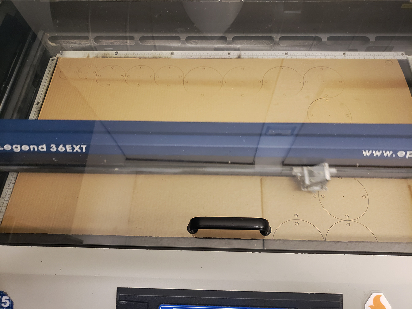
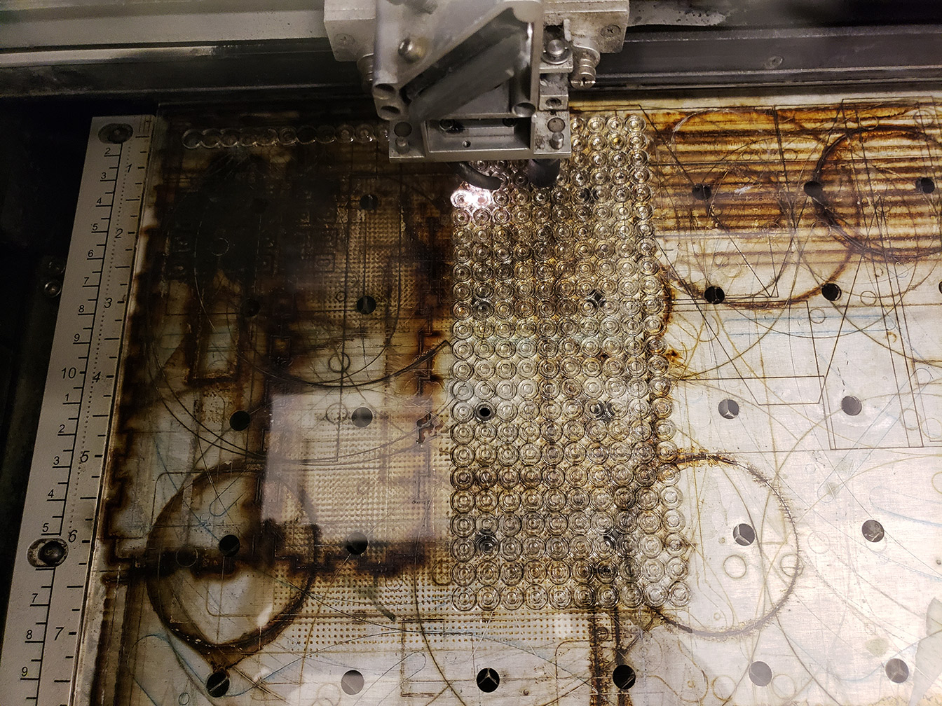
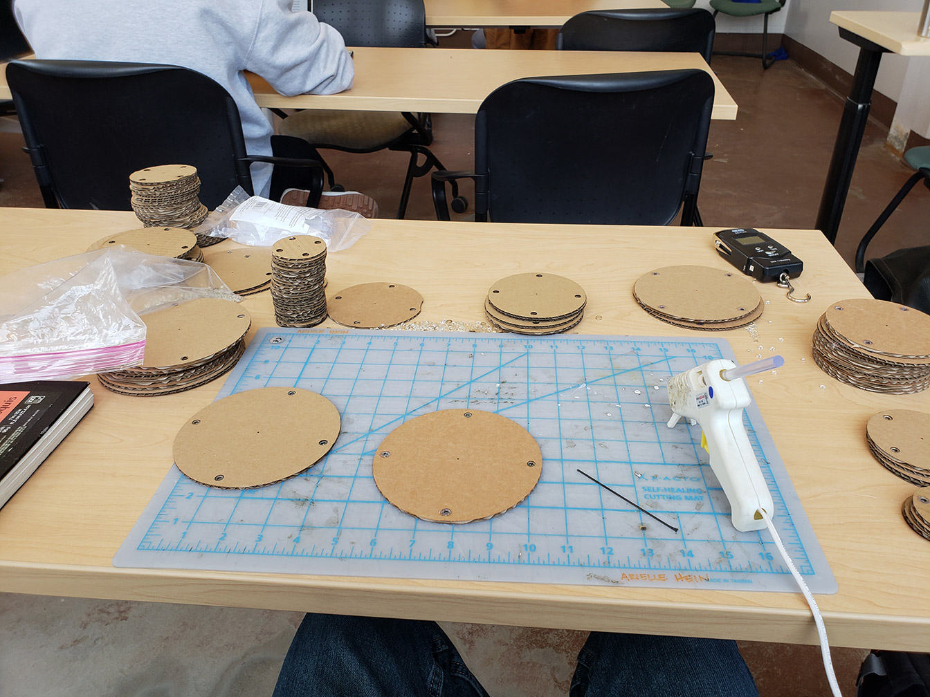
I started by doing some looking around to source a good core material for the legs. I found a kite store on Pearl Street that had fiberglass and carbon fiber rods for kite building that looked perfect. I got a 1/16" fiberglass rod, a 0.05" carbon fiber, 0.06" carbon fiber, and a 0.07" carbon fiber rod. My large scale prototype from last semester was big, heavy, and couldn't support it's own weight. The carbon fiber and fiberglass are super light and range from the fairly flexible 1/16" fiberglass up to pretty stiff at the thickest carbon fiber. From here, I wanted to find an optimal geometry for the construction of the leg. To this end I laser cut a bunch of cardboard discs in different sizes and cut and glued plastic spacers to line the holes to prevent the fishing line from tearing through.
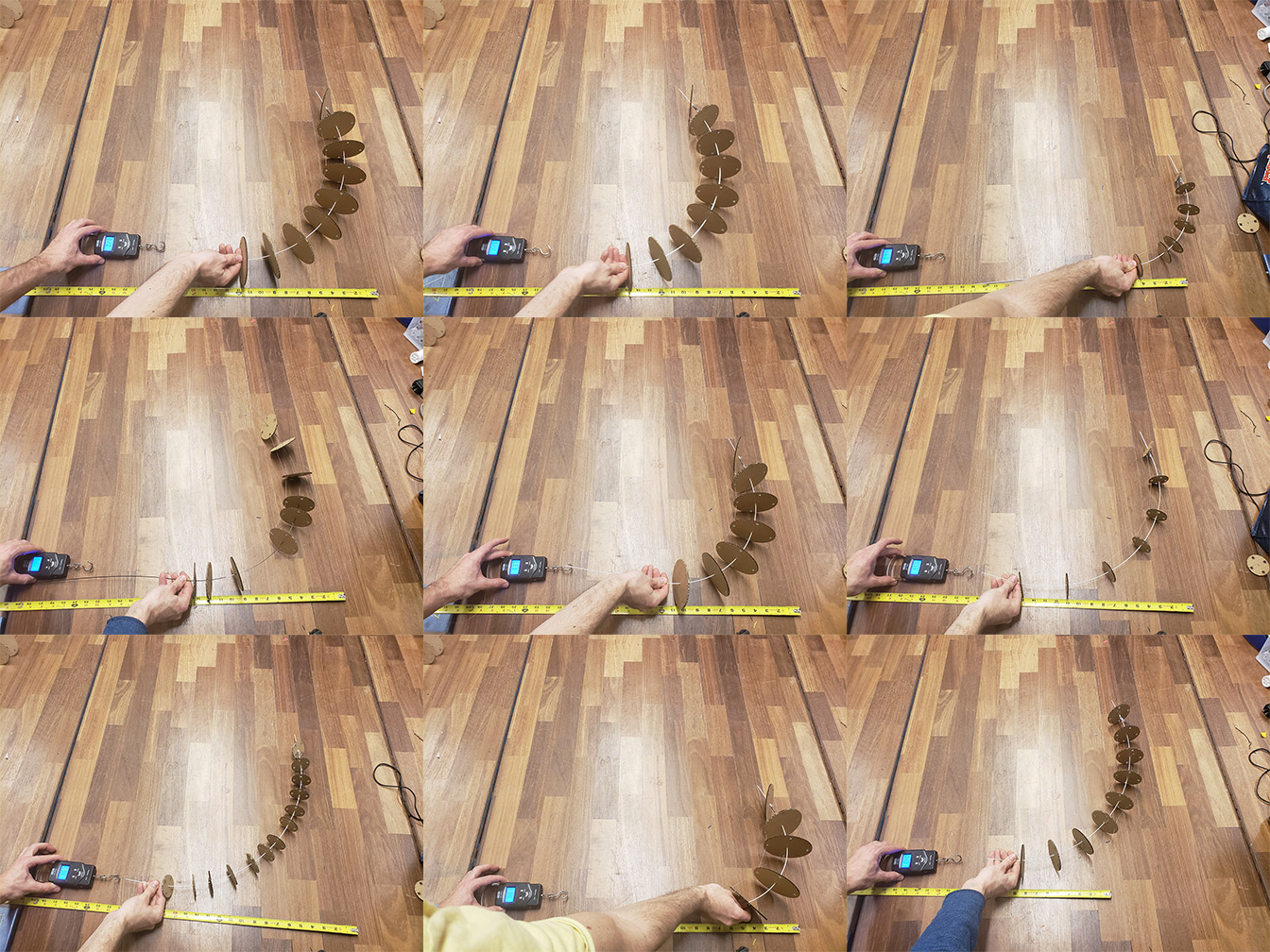
I then took the fiberglass rod and tried different variations on the size of the discs, the spacing, and the overall length of the leg. To evaluate each configuration, I measured the distance you had to pull the fishing line to bend the leg to ~90 degrees, and the maximum force required.
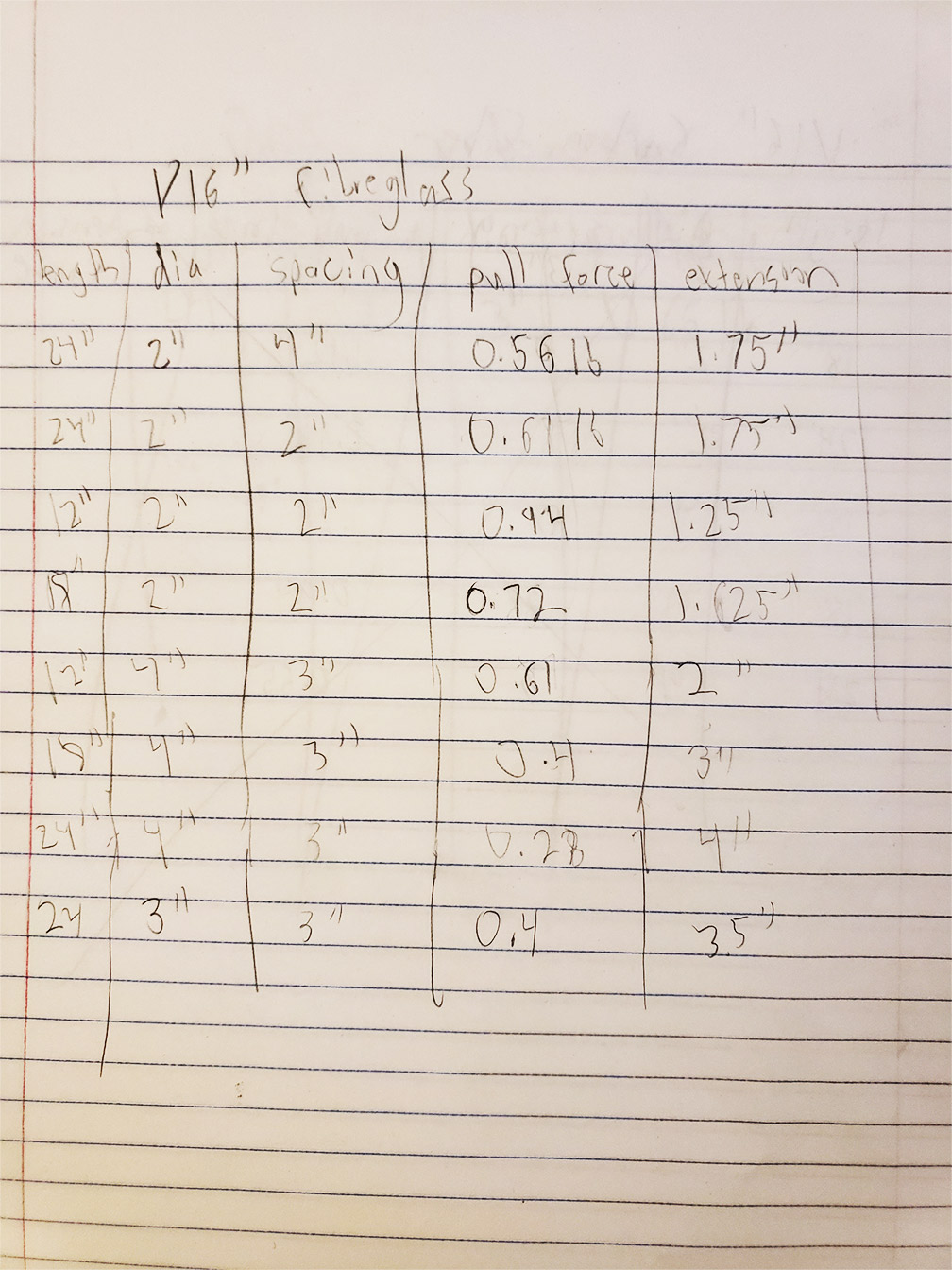
Results:
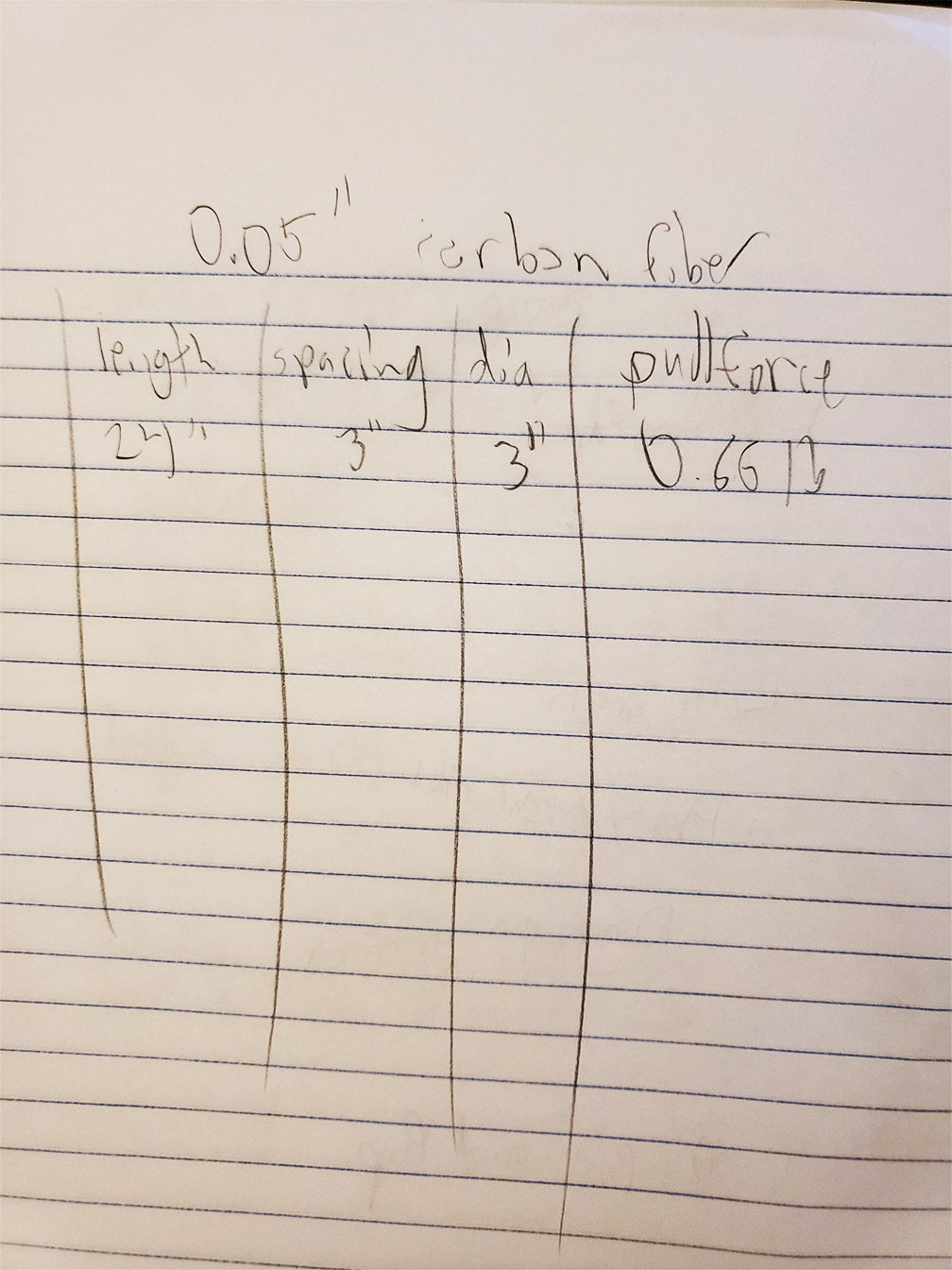
I learned that firstly, the spacing of the discs hardly matters (within reason), so that choice is largely aesthetic. The longer the leg, the less force is required to bend it, but also the less weight it can support, since the weight is pressing on a longer lever. Lastly, the diameter of the disc acts as choosing mechanical advantage, with smaller diameters bending more for less fishing line pulled but at a higher amount of pull force, and large diameters functioning the opposite. I'm attaching the fishing line to a pulley to drive it, so I can vary the diameter of the pully to fine tune the balance of torque and speed, so this makes the choice of diameter an aesthetic one as well. I decided I liked the 3" diameter disc and 3" spacing with a 24" overall length. This has a nice size in terms of the width to length ratio, as well as it didn't take up too much material in laser cutting. I only ran one test for the carbon fiber since I was trying to make the leg as light and require as little force to operate as possible. The fiberglass and the 0.05" carbon fiber were the most flexible materials I had, and the carbon fiber was stiffer, so I went with the fiberglass. After determining that I was going to be dealing with around 0.4 lb of force, I started by ordering the fs90r continuous servo by Feetech. It has a torque of 1.5kg-cm, and is feather light at only 9 g. Converting to pounds to match the units of my measurements, this is 1.3 lb-in. This servo spins at roughly 2 revs/second. Lets say I wanted the leg to go a full 180 degrees in 0.5 s, that would require the pull distance of the 3" diameter 3" spacing (3.5 inches) to equal the circumference. This yields radius of 0.56", and I rounded up a bit to 0.75", since even at 0.75 the theoretical max pull force by this servo is 1.73 pounds, more than enough. Given all this, I had all the information I needed to draft up a drive mechanism. The capstan and bowstring mechanism makes the most sense to me for this purpose. I measured up the dimensions of the servo and the attachment hardware and this is what I came up with:
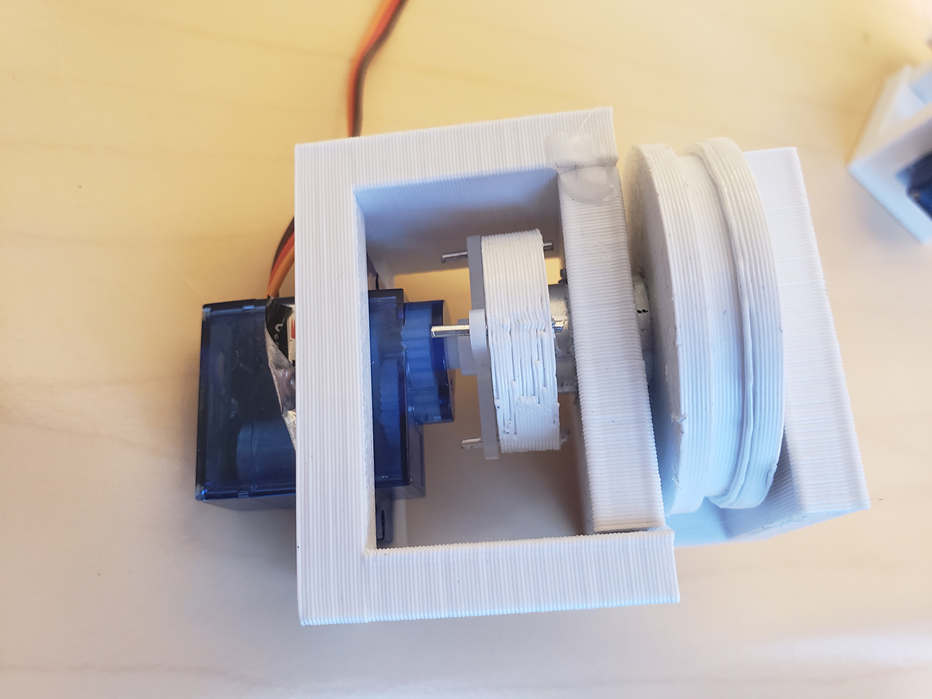
Then I 3d printed 2 of all the parts (1 for x, 1 for y), and assembled, and this is the result:
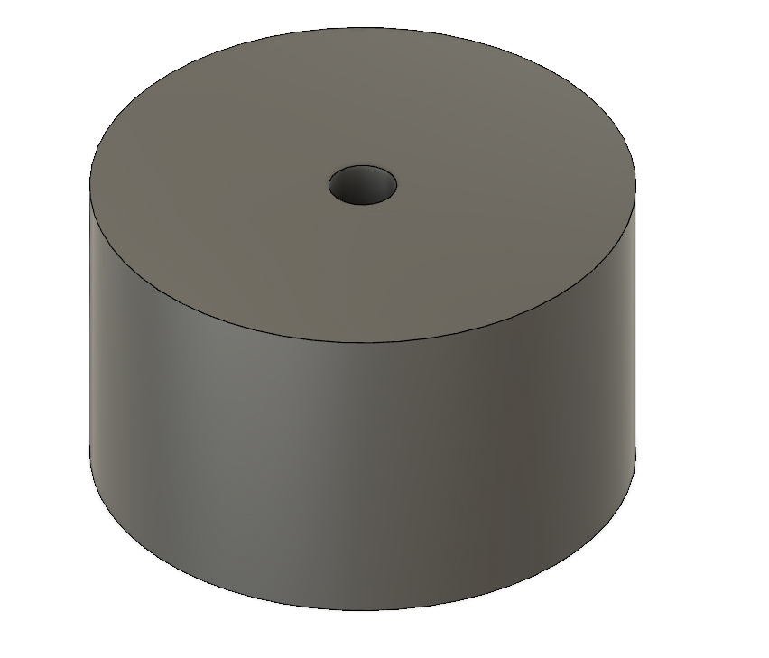
For the leg itself, Daniel suggested Delrin plastic, since it cracks less easily than acrylic, and the high torque forces around where each disc is attached to the rod could be problematic for that reason. I got some acetal copolymer, which is chemically quite similar to Delrin. I also widened the center hole of the discs and designed a shaft collar to go in between to alleviate this further. Here's the vector file for the 3" discs:
Collar
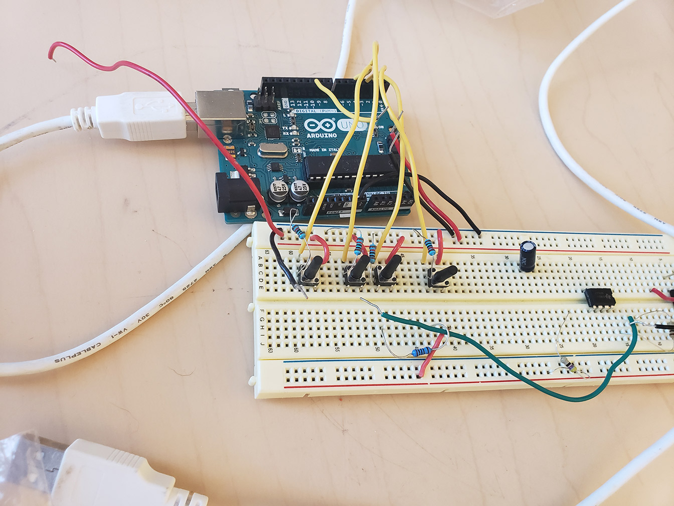
I whipped up a quick circuit with an arduino to drive the servo. It has 4 buttons with pulldown resistors hooked up to pins 2-5, intended to drive 2 servos off of pins 9 and 10 using the servo library, though I only hooked up one for now. One button rotates clockwise and the other counter clockwise for each servo.
#include
Servo myservo; // create servo object to control a servo
Servo myservo2; // create servo object to control a servo
void setup() {
myservo.attach(9); // attaches the servo on pin 9 to the servo object
myservo2.attach(10); // attaches the servo on pin 9 to the servo object
pinMode(2, INPUT);
pinMode(3, INPUT);
pinMode(4, INPUT);
pinMode(5, INPUT);
}
void loop() {
if(digitalRead(2))
{
myservo.write(0); // 0 and 180 rotate at full speed, 90 stops
}
else if(digitalRead(3))
{
myservo.write(180);
}
else
{
myservo.write(90);
}
if(digitalRead(4))
{
myservo2.write(0);
}
else if(digitalRead(5))
{
myservo2.write(180);
}
else
{
myservo2.write(90);
}
delay(20);
}
Some assembly later, I ended up with a decently working result:
I certainly learned a lot working my way through the process of designing and fabrication. Firstly, while the servo and pully I picked may have been alright for static measurements, I didn't take into account momentum. The servo struggled in accelerating and deccelerating the leg, and I also didn't account for the effect of weight. With everything put together, the fiberglass is pretty weak and can't really support even its own weight. From here, it's looking like I'll have to bite the bullet and get some beefier servos and use a thicker, carbon fiber core so it can better support itself and cope with its weight. I also learned that the acetyl copolymer has internal stresses that release under heat, which is a problem when laser cutting. This caused the sheet to twist and warp as it was being cut, and about half of the discs I cut were borderline unusable thanks to intersecting cuts. I talked to Danny, and he said that he thought this plastic was a good choice of material, and he suggested I cut it with CNC instead of a laser to work around this problem. Despite the need for tweaks, the overall leg design seems solid. Worst case, Daniel suggested that I have the bot ride on wheels and just use its limbs to push itself around, removing the need for it to support its own weight. This is a good backup plan, but it's not as cool as a walking, jumping, dancing robot.
Prototypes 2
Functional Leg Model
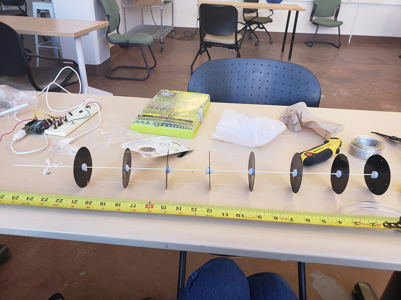
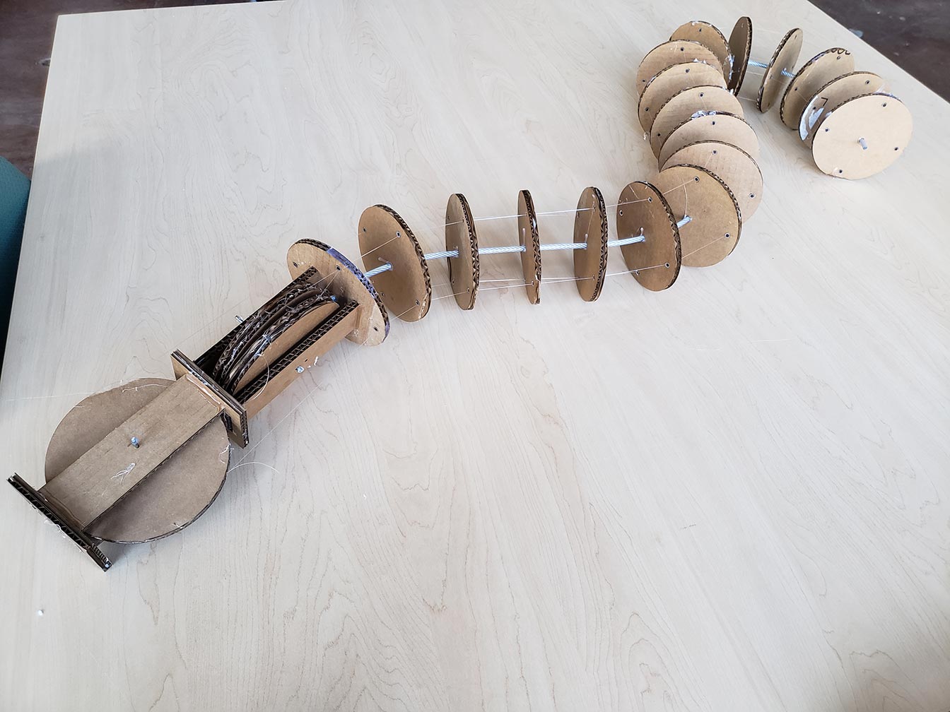
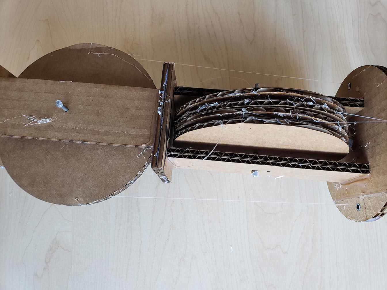
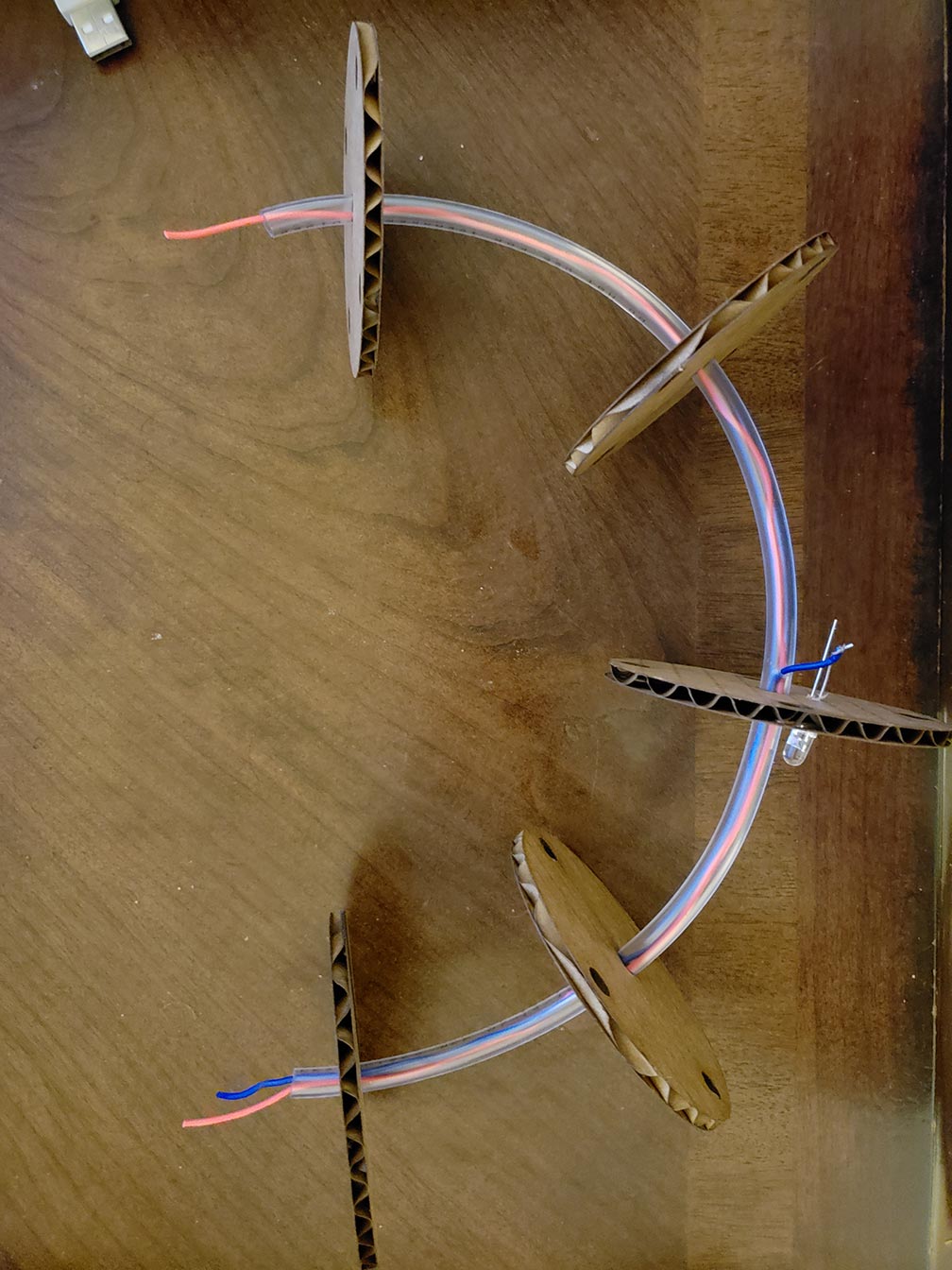
I made a full sized, functional prototype of the leg to understand the challenges I would face at larger scale as well as to test the mechanism I had in mind. I laser cut 18 cardboard circles and spaced them every 3" along a 54" steel cable. I put sections of 1/4" OD acrylic tubing inside of the outer holes of the cardboard sections to protect them from getting cut by the fishing line. I then ran 4 lengths of fishing line through each of the 4 holes on the cardboard sections from the end of the leg all the way to the control pulleys at the top, tensioned them, and tied them off around the circumference of the pulleys. Turning the pulleys allows me to adjust each axis of motion independently. I learned a few things from this excercise. Firstly, 54" inches is rather large and heavy, so I think I'll have to reduce the size by 33% to 50%. I aligned all the discs by hand, so they aren't perfectly in line, which causes the whole thing to coil up into a helix rather than just bend. This may also be a natural behavior of the system, in which case I'll have to figure out a way to control it better. The motion tends to concentrate around the end of the leg farthest from the pulleys rather than distributing evenly along its length. I also attached a third pully that goes halfway down the length of the leg, and the effect is even more exaggerated with the weight of the leg hanging off the end of the tension point. Changing the size and spacing of the discs may help this as well, so I'll have to keep protyping to see what works. Worst case, if I can't get better control I'll have to go with a more traditional leg design with rigid bones and a mechanical knee.
Wire/Light Mounting
This was a quick little experiment to try running wires along a model of the leg. The leg is flexible, so the wires need to be able to bend along with whatever shape the leg is in. Originally, I was thinking I could just feed an LED strip through a tube in the center, but I realized that they only bend along one axis, which wasn't going to cut it. The design I settled on was substituting acrylic tube for the steel cable I used in the above prototype. This allowed me to run the wires right through the middle. I can then mount each led (or set of leds) to each disc, and I can drill holes in the tubing to connect power, ground, and the data stream to the led. In this prototype, I put a regular led on there, but when I'm ready to build the real thing I'll use WS2812B leds so I can drive all of them in series. I will be limited by how many wires I can fit inside the tube, so I'll have to size the core accordingly. Another option would be to run the wires along the outside of the core to similar effect. When I'm ready to spend a little more time, I could also fabricate a strand of LEDs by hand, and connect each WS2812B chip with wires and run that through the center tube. That would probably be the neatest, and having them connected by wires instead of a strip would allow them to bend along two axes.
Transient Visualizer
I put together as simple a music visualizer as I could. I chopped an eighth inch audio cable in half and plugged the left channel and ground right into A0 and GND on the Arduino, respectively. I wrote a program to take a reading, store it, take another, and compare it to the previous reading. It does this over and over and when the current reading is a threshold value higher than the previous reading, that indicates that there was a sudden spike, or a transient, and it triggers the lights to flash. I learned that I'll have to calibrate the sensitivity of the input on the fly to account for different volume levels, since changing the volume right now will cause it to be too sensitive or to not trigger at all. I think I'll be able to create some interesting effects using a similar algorithm to what I have now, but by detecting transients over different frequency ranges using an FFT. I also noticed that going from just sampling audio to sampling audio and driving a single, blinking LED strip caused a pretty significant decrease in the sampling rate, so I'll definitely have to find a microcontroller with more computing power, or possibly have one microcontroller dedicated to driving the lights and one dedicated to audio analysis.
Prototypes 1
Scale Model
To explore the look and feel of the project, I made a 1:4 scale model of the overall shape of the robot. I wanted to answer the question of what this thing is going to look like and what proportions I'm dealing with. It also gives me a way to communicate the idea in my head. As it stands, I'm happy with the overall look, so I don't think any major adjustments are needed yet.
Appendage Prototype
This was designed as an initial foray into implementation, specifically to figure out how the arms are going to articulate. I made a few discs separated by cardboard spacers of different sizes, and ran fishing line along its length through all the discs. Tensioning the wires causes the appendage to bend in different directions. The main problem is the spacers offer too much freedom of movement for each disc where they are joined, so I learned that picking an adequate core material is going to be key to making the arms work. I went to the hardware store and walked up and down the isles bending rods, tubes, and cables until I settled on some steel cable. It's flexible, but it won't collapse in on itself, so I'll be making my next prototype with steel cable as the core. One other problem I found was that the fishing line is cutting through the cardboard, which won't be an issue in the final project since it'll likely be made from acrylic, but for prototyping I got some plastic tubing to line the holes to prevent this in future prototypes.
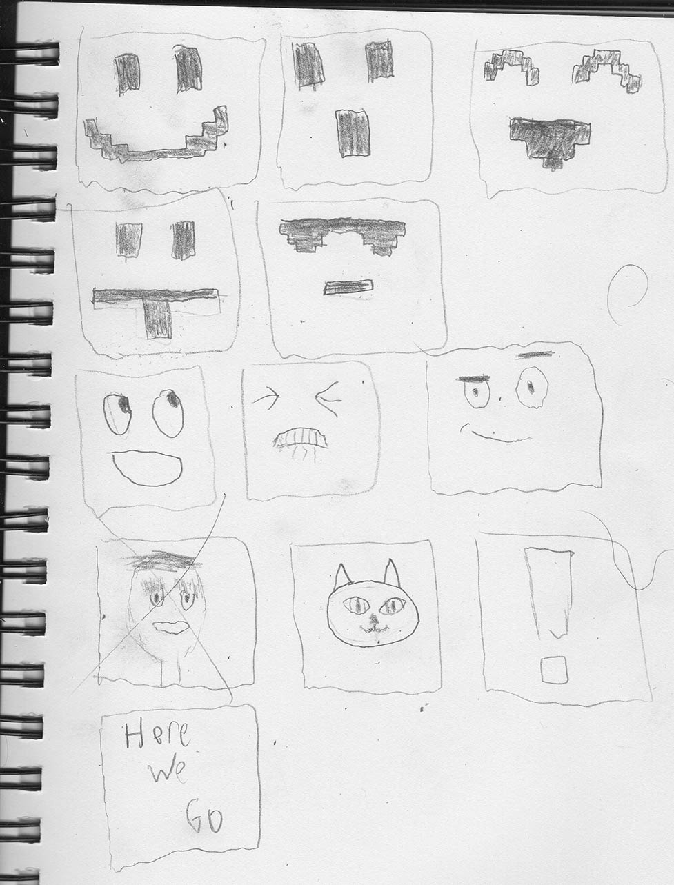
Face Sketches
Lastly, I looked at the role this thing is going to play. I want this robot to be more than just another pre programmed light show. I want it to feel like it's dancing and having fun along with all the other people, and in order to make a robot seem fun, people will need to be able to empathize with it and project their own feelings onto it. In order to do that, I'm going to give it a face. As I've been learning in cognitive science, people really gravitate towards faces, even when it's a screen or objects that just happen to look like a face. I played with a few different styles, and so far I like the retro, pixelated style the best. The regular, cartoony faces are okay, and trying to put a head on the display just creeped me out. I think there is also potential with occasionally flashing messages or symbols as a form of expression.
Concept Validation Interviews
My project idea at this point is to create a robot to dance and light up in response to music. The bot will be about 3.5 feet tall, 5 feet wide, and 5 feet long with six independently controllable, flexible legs connected to a central, hexagonal body that is around two feet in diameter and a foot tall. The legs will have lights running their length; The body will have a laser projector mounted on top, and a screen with a face on the front to allow people to empathize with it more. It will have a microphone with real time audio processing that will allow the robot to detect and analyze music playing in the environment. This will allow the robot to keep in time with the music, to change the kind of light show and dancing to match the style of music, and to transition between different animations to match the musical phrasing. Where classical music may induce a gentle swaying and bobbing with lights that ripple and fade smoothly, dubstep could cause flashing lights while the bot fist-pumps and head-bangs.
Invterviews
Jiffer Harriman
He’s done a few interactive installations, and his approach is designing interactions that are easy to understand and interact with, playful, and inviting
He recommended that to start, I focus on basic movement and not walking/mobility.
The aspect of both mechanical and light based visualization was compelling
I could have the legs be on wheels instead of feet for ease of movement
An Arduino won’t be powerful enough for real time audio processing; he recommended a Teensy, a Raspberry Pi, or a Beagle Bone Black, which has Bela cape specifically for audio processing
He suggested using both transients and a FFT to analyze frequency for cuing audio, and to have different effects based on different bands of frequencies having more or less amplitude
Use off the shelf components wherever possible for the sake of simplicity and time
Watch out for electrical noise on longer wires
Watch for power spikes and voltage drops and generally make sure the design can handle all the devices when working with lots of high current devices (motors)
Leave lots of time for iterating
Daniel Leithinger
Offload some of the electrical/actuator complexity to mechanisms, and he showed me Arthur Jansen’s beach creatures and the Land Crawler Extreme
He gave me the idea to have the audience be able to push the robot around or turn it on with a crank
I could have it move around with vibration instead of having to walk, and he showed me the Nintendo Labo rc car that does just that, as well as Danel Sankes moving furniture
I should keep in mind that people might intentionally or accidentally mess with the robot, so it should be robust in its design.
The robot should have personality
Instead of one robot, I could have a swarm of little vibrating robots that scatter all over the floor and light up
Cardboard can be quite strong when multiple layers are glued together with the different layers being rotated at 90 degrees, so it would be great for building prototypes, and might even be something to look at for the final design since it’s cheap, strong, and lightweight.
The robot could be a “one man band”, or something that can throw a party all by itself
Michael Theodore
Suggested IR rangefinders to sense proximity and allow interaction at a distance
Gave me a servo in the price range I would be looking at to test with
I could use a node based design where each leg has some of it’s own circuitry to offload some of the demand from the central computer
Top 8 Ideas
Here are my 8 favorite ideas that came out of brainstorming. I haven't restricted them by feasibility, so some of them may be too ambitious for me to take on.
1. Dancing robot
So far my favorite idea, this would be a humanoid robot with two legs and two arms that can dance. Ideally it would be as large as a person, maybe a bit bigger, in the range of 6-7 feet tall, but really I would build it as large as I could afford to. The key to that is building it as light as possible because the smaller the actuators I can get away with, the cheaper it will be. The technical challenge is obvious; it would require the coordination of many actuators along many axes of movement, and many sensors to measure the position and forces at the joints and the center of mass. For the theoretical, it would require some calculus based physics to figure out how to maintain balance while in different positions, taking into account both the position and orientation of the limbs as well as the momentum. And that's just to stay upright. To dance, I would have to analyze the movements that go into dance and translate it into an implementable algorithm that the machine can follow. This also bleeds into design. I would say that the dancing component falls into all three categories, involving the aesthetic element of dance, and the theoretical and technical challenge of analyzing and quantifying dance. There is also the design of the robot itself; I was thinking I could make a plastic shell to house it and make it look clean and professional.
2. Light Suit
This would be a wearable music visualizer. Panels of lights would be worn head to ankle, fitted to the body. It would have to have joints to be able to move. The source for visualizing could either be audio, and all the visualization would be done on board, or the suit could recieve data over a video connection and the visualization would be done on a computer. This second option would also allow for pre-made light shows, like the ones already used in shows. The technical aspect would be all the electronics for driving all the lights, the theory would involve doing the visualization, and the design would be making the suit look cool and coming up with interesting visualizations.
3. Drone Light Show
This would consist of a (scalable) number of drones all connected to a central computer that coordinates their movements. Each of the drone has lights, and they all fly around to create an aerial light show. The technical aspect would be tracking the position of all the drones and autonomously piloting them, I dunno what the theory would be, and the design would involve the appearance of the drones and lights and how to turn a bunch of drones flying around into a performance people would want to watch.
4. Abstract morphing robot
More of an art piece than anything else, this would be a modular robot that could freely reassemble and morph itself into different shapes and motions based on response to proximity, sound, touch, etc.
5. Portable AR/VR System
A positioning system based on time of flight (similar to gps) rather than a lighthouse system. The lighthouse system (what the vive uses) has limited range and requires line of sight to both base stations. Instead, have 4 sensors a few meters apart that each measure the time it takes to send a signal to the tracker on the headset/controllers, use that to calculate distance, and then use the distances to each of the sensors at a known position to calculate position. This would allow the VR/AR space to be much larger (as large as the range on the wireless), and would allow it to be set up anywhere with a laptop.
6. Music Analyzer and Recommender
Most music recommendation algorithms are based on user data and general categorizations rather than any understanding of the music itself. My idea is to perform a structural analysis of the music (tempo, rhythmic patterns, harmonic progressions, phrasing) and to find similar music based on those attributes.
7. Magnetic Levitation Juggler
Adapt mag-lev technology to levitate and move around objects in 3d space. Intended as a decorative piece.
8. Wings
I love the idea, which is why I included it here, but I don't think it's feasible for the amount of time and resources currently at my disposal. It would be a set of mechanically assisted wings that I could use to fly around. I would start by getting some data from birds (wing surface area, coefficient of lift, and mass of the bird) to get a general idea of how big they would have to be and what shape. I would then make a mechanical keel I could strap into. The keel is why birds have a protruding chest; it is a bony protrusion (to give leverage) wrapped in a bunch of tough and strong muscle that gives birds the needed strength to flap their wings. It would likely be some big gears/pullies attached at the joint of the wing driven by a smaller gear/pully attached to a motor.