Originally, the code looked for the most blocked pair of sensors to determine where to draw on the grid. It would read in all the analog values and compare them, and the highest value was the point where it would draw a pixel. This lead to some erratic behavior, which I believe was caused by the fact that I ran out of 100k resistors and had to substitute other values in some spots. This meant that certain pairs were more sensitive than others, and would be more likely to activate than surrounding rows and columns. This method also meant that you could only draw one pixel at a time. After doing some user testing at the ATLAS expo, I found out people really wanted to put their entire hand on the grid and light up all the lights at once.
I started the refinement process by making the program look for any blocked sensors rather than the most blocked. This meant that the program could support multi touch and set larger areas at once. This approach worked well, but introduced a few new issues. It was really difficult to set just 1 LED, since a finger was wide enough to trigger multiple sensors at once. This algorithm was also more sensitive to noise, and occasinally random LEDs would light up in the corners when drawing elsewhere on the grid.
Now that I had a better idea of what I was working with and had some new goals, I decided to take a more sophisticated approach to interpreting the sensors. I ended up with a clustering algorithm that would find contiguous groups of blocked sensors and return their center and size, giving me much more control over the interpretation. The current version ignores clusters of size 1, which removes the noise problem. Clusters of size 2-4 will draw one point in the center of the cluster, allowing for precise drawing with one finger. Clusters of 5 or bigger will light up everything in that cluster, so using multiple fingers or a hand will still light up a large area. Lastly, this approach still supports drawing with multiple fingers at once. After some testing, I realized that this method made it hard to draw around the edges of the grid since the sensors end at the edge of the grid and clusters of size 1 are ignored. Throughout the whole process, the edges and corners have always been the most problematic, and I think the best solution would be to increase the size of the sensor arrays to extend past the end of the grid. That solves the problem of too little sensitivity around the edges. This would require a pretty significant redesign, though, since I'm currently at exactly 32 sensors going into a 32 to 1 mux, so increasing the number of sensors would require another mux, new circuit boards, and some tweaks to the software. I'm happy with where it's at now, and I think the next step would be to come up with some more interactions. I've essentially build my own touch screen, so I feel there is more to explore than just a drawing application.
The matrix driver code is unchanged, here is the new clustering code:
#include "matrix_driver.h"
#define CLUSTER_MATRIX_SIZE 6 //number of clusters for each axis
int irPin = 5; //pin for reading ir from multiplexer
int irSelectStart = 3; //start of 5 contiguous pins ascending for selecting mux, eg 1 will use pins 1-5
int rpot = 0; //analog pot pins
int gpot = 1;
int bpot = 2;
int rled = 9;
int gled = 10;
int bled = 11;
int reset = 12; //reset button
int detectorThreshold = 70;
int rval,gval,bval;
int irArray[32]; //array for holding values from ir sensors
unsigned int base[32]; //base readings from ir diodes
int activeSensors[32]; //for returning active sensors
int clusters[2][CLUSTER_MATRIX_SIZE][2]; //stores found clusters, [0][b][c] is clusters along x, [1][b][c] is y, [a][b][0] is location, [a][b][1] is size
Matrix grid(2);
void updatePreview(int r, int g, int b)
{
analogWrite(rled,r);
analogWrite(gled,g);
analogWrite(bled,b);
}
int readIR(int select) //read 1 IR sensor
{
PORTD &= (~0) & (~(0x1F<<irSelectStart)); //clear select bits
uint8_t outByte = (select & 0x1F)<<irSelectStart; //get lower 5 bits from select, then shift to desired range
PORTD |= outByte;
return analogRead(irPin);
}
void getIR(unsigned int* arr) //read all IR sensors, weird logic due to the wiring going to the mux
{
int cnt = 7; //decreasing counter
int cnt2 = 8; //increasing counter
for(int i=0; i<16; i+=2)
{
arr[i] = readIR(cnt);
arr[i+1] = readIR(cnt2);
cnt--;
cnt2++;
}
cnt = 24; //now read y axis, directions flip due to pcb mirror, so cnt is increasing
cnt2 = 23; //now decreasing
for(int i=16; i<32; i+=2)
{
arr[i] = readIR(cnt);
arr[i+1] = readIR(cnt2);
cnt++;
cnt2--;
}
}
void getActiveSensors(unsigned int* avg, int* cur, int* activePoints) //takes base and current sensor readings and figures out which sensors are active
{
int tmp;
for(int i=0; i<32; i++)
{
tmp = cur[i]-avg[i];
//Serial.print(tmp);
//Serial.print(" ");
if(tmp>detectorThreshold)
{
activePoints[i] = 1;
}
else
{
activePoints[i] = 0;
}
}
//Serial.println("");
}
void getClusters(int* activePoints, int clusterCenters[2][CLUSTER_MATRIX_SIZE][2]) //takes active sensors and groups them into contiguous clusters, returns location and size of these clusters
{
for(int i=0; i<CLUSTER_MATRIX_SIZE; i++) //clear matrix for storing found clusters, -1 indicates empty
{
clusterCenters[0][i][0] = -1;
clusterCenters[1][i][0] = -1;
}
bool foundCluster = false; //is a cluster currently being analyzed
unsigned int clusterSize = 0; //accumulator for cluster sizes
unsigned int clusterIndex = 0; //keeps track of current index for output
for(int j=0; j<=16; j+=16) //loop for each axis
{
clusterIndex = 0;
for(int i=0; i<16; i++) //loop for each point
{
if(activePoints[i+j])
{
foundCluster = true;
clusterSize++;
}
if((!activePoints[i+j]) || (i==15)) //terminate cluster if activePoints is 0 or it hits the end of the display
{
if(foundCluster)
{
int c; //constant for shifting slightly right when cluster is right of center
if(i>=8)
{
c=1;
}
else
{
c=0;
}
clusterCenters[j>>4][clusterIndex][0] = i-((clusterSize-c)>>1)-1; //j<<4 to divide by 16, set cluster location to i-(size/2)
clusterCenters[j>>4][clusterIndex][1] = clusterSize;
foundCluster = false;
clusterSize = 0;
clusterIndex++;
}
}
}
}
Serial.println("");
}
void calibrate(unsigned int *arr)
{
int readCount = 16; //number of readings to take per sensor
unsigned int buf[32];
for(int i=0; i<32; i++)
{
arr[i] = 0; //zero out everything
}
for(int j=0; j<readCount; j++)
{
getIR(buf);
for(int i=0; i<32; i++)
{
arr[i] += buf[i];
}
}
for(int i=0; i<32; i++)
{
arr[i] = arr[i]>>4; //divide by number of readings, in this case shift right to divide by 16
}
}
void setup() {
noInterrupts();
grid.setAll(0,0,0);
DDRD |= 0x1F<<irSelectStart; //set pins as output for multiplexer
pinMode(reset, INPUT); //enable reset button
Serial.begin(9600);
getIR(base); //run twice to warm up
calibrate(base);
}
void loop() {
rval = analogRead(rpot)>>4;
gval = analogRead(gpot)>>4;
bval = analogRead(bpot)>>4;
updatePreview(rval,gval,bval);
getIR(irArray); //get raw readings from sensors
getActiveSensors(base,irArray,activeSensors); //find active sensors
getClusters(activeSensors,clusters); //group active sensors into clusters
int indx = 0;
int indy;
// for(int i=0; i<2; i++)
// {
// for(int j=0; j<CLUSTER_MATRIX_SIZE; j++)
// {
// Serial.print(clusters[i][j][0]);
// Serial.print(" ");
// Serial.print(clusters[j][j][1]);
// Serial.print(" ");
// }
// }
while(clusters[0][indx][0] >= 0) //loop over x clusters, -1 indicates empty so it loops until it reaches an empty slot
{
indy = 0;
while(clusters[1][indy][0] >= 0) //loop over y clusters
{
if((clusters[0][indx][1]>4) && (clusters[1][indy][1]>4)) //if cluster is large, draw whole thing
{
int xstart = constrain(clusters[0][indx][0]-(clusters[0][indx][1]>>1),0,15);
int xend = constrain(clusters[0][indx][0]+(clusters[0][indx][1]>>1),0,15);
int ystart = constrain(clusters[1][indy][0]-(clusters[1][indy][1]>>1),0,15);
int yend = constrain(clusters[1][indy][0]+(clusters[1][indy][1]>>1),0,15);
for(int i=xstart; i<=xend; i++)
{
for(int j=ystart; j<=yend; j++)
{
grid.setElement(i,j,rval,gval,bval);
}
}
}
else if((clusters[0][indx][1]>1) && (clusters[1][indy][1]>1)) //if cluster is smaller than 5, draw 1 point in the center, if it's smaller than 2, don't draw at all to ignore noise
{
grid.setElement(clusters[0][indx][0],clusters[1][indy][0],rval,gval,bval);
}
indy++;
}
indx++;
}
if(digitalRead(reset)) //clear and re callibrate if reset is pressed
{
grid.setAll(0,0,0);
calibrate(base);
}
grid.update(); //write new data to grid
}
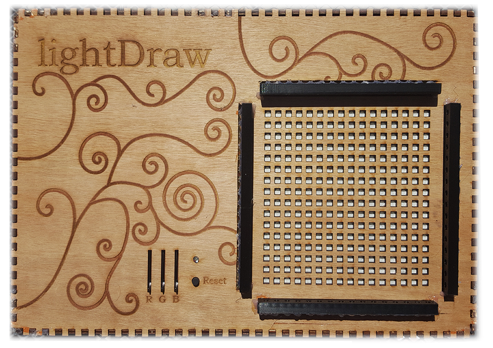
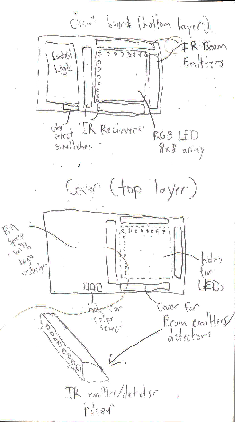
This project features a 16x16 grid of individually programmable LEDs that you can draw on using a finger. The 3 sliders control what color you draw with, and the LED next to them shows a preview of that color. The 4 black rails on the top, bottom, and sides contain all the sensors for determining finger position.
Circuitry
The bottom and right rails hold 16 IR LEDs each which are just hooked up to power, and the top and left rails hold 16 IR phototransistors in the following circuit:
The schematic is a little unclear due to all the overlapping wires, but each phototransistor is connected through a 100k resistor to power, and the other end is connected directly to ground. This acts as a voltage divider, and since the phototransistor will change impedence as the amount of light it recieves changes, the voltage in the middle of the divider will change as well. This point where each phototransistor is connected to the resistor is connected to 1 pin on a ribbon cable header. This connects via a ribbon cable to a 32 to 1 multiplexer to be read into an Arduino. A multiplexer is a device that allows many inputs to be read one at a time into 1 input pin. Multiplexer circuit:
There are two arrays of 16 phototransistors, one for each axis, and they both feed into the multiplexer inputs S1-S32. A0-A4 are the selector inputs, effectively accepting a 5 bit "address" to pick which one of the inputs are connected to D, the data output. For example, to read pin 10, the Arduino would set A0 to high, A1 to low, A2 to low, A3 to high, and A4 to low. A0 is the least significant bit, so this translates to address 01001 in binary, or 9 in decimal. This is because the pin numbers start at 1, but the addresses start at 0, so to select input 1 you have to put in all 0s, to get input 2 you put in 0001, and so on. Then the Arduino would analogRead from D, and it would store that value. The end result is when a finger is placed in the sensor array, a phototransistor on the x axis is blocked and changes value and a phototransistor on the y axis is also blocked and changes value, and putting these two together allows the Arduino to determine where the finger is placed.
Software
I wrote the library for interfacing with the LED grid myself. The grid is a chain of WS2812B LED drivers, and this IC requires data to be input at exactly 800kHz. For the nitty gritty details of the timing and order of data, you can see the datasheet here. I used the program Atmel Studio to tune the timing of the program, since it has a simulator that keeps track of exactly how many clock cycles have elapsed for every line of code, and using this I can figure out how much additional delay is needed on top of how long it takes to execute each write instruction. I used NOPs to add delay, which is an assembly instruction that causes the microcontroller to delay for 1 clock cycle, so it allows for extremely precise control. I also bypassed the Arduino libraries, which add a significant amount of overhead and extra delay, and instead wrote directly to the relevant registers. The details of the hardware of microcontrollers, programming for avr, and assembly are a bit beyond the scope of this post, so for now I'll just move on. The library exposes an object Matrix, which has functions for setting individual lights, rows, columns, or the entire matrix. It also handles 2D addressing to what is essentially a string of LEDs shaped like a grid, and has a function update to write out all of the new data to update the display.
Matrix driver header:
#ifndef MATRIX_DRIVER_H
#define MATRIX_DRIVER_H
#define X_DIM 16
#define Y_DIM 16
typedef unsigned char uint8_t;
struct pixel{
uint8_t g;
uint8_t r;
uint8_t b;
};
class Matrix {
public:
//Matrix(int dataPin, int xdim, int ydim);
Matrix(int dataPin);
void update();
void setElement(int x,int y, pixel);
void setElement(int x,int y, int r, int g, int b);
void setColumn(int x, int r, int g, int b);
void setRow(int y, int r, int g, int b);
void setAll(pixel);
void setAll(int r, int g, int b);
int xdim();
int ydim();
private:
void writeByte(uint8_t);
int _xdim, _ydim;
int _length;
pixel _grid[X_DIM*Y_DIM];
uint8_t _dataPinOn;
uint8_t _dataPinOff;
};
#endif
Matrix driver code:
#include "matrix_driver.h"
#include <avr/io.h>
Matrix::Matrix(int dataPin) //datapin 0 through 7 corresponds to d0-d7 on the uno
{
_xdim = X_DIM;
_ydim = Y_DIM;
_length = X_DIM*Y_DIM;
_dataPinOn = (uint8_t)1<<dataPin;
_dataPinOff = ~_dataPinOn;
DDRD |= _dataPinOn;
}
int Matrix::xdim()
{
return _xdim;
}
int Matrix::ydim()
{
return _ydim;
}
void Matrix::setElement(int x, int y, pixel p)
{
if(x%2)
{
_grid[((x+1)*_ydim) - 1 - y] = p;
}
else
{
_grid[(x*_ydim) + y] = p;
}
}
void Matrix::setElement(int x, int y, int r, int g, int b)
{
int index;
if(x%2)
{
index = ((x+1)*_ydim) - 1 - y;
}
else
{
index = (x*_ydim) + y;
}
_grid[index].r = r;
_grid[index].g = g;
_grid[index].b = b;
}
void Matrix::setColumn(int x, int r, int g, int b)
{
for(int i=0; i<Y_DIM; i++)
{
this->setElement(x,i,r,g,b);
}
}
void Matrix::setRow(int y, int r, int g, int b)
{
for(int i=0; i<X_DIM; i++)
{
this->setElement(i,y,r,g,b);
}
}
void Matrix::setAll(pixel p)
{
for(int i=0; i<_length; i++)
{
_grid[i] = p;
}
}
void Matrix::setAll(int r, int g, int b)
{
for(int i=0; i<_length; i++)
{
_grid[i].r = r;
_grid[i].g = g;
_grid[i].b = b;
}
}
void Matrix::update() //write _grid to display
{
for(int i=0; i<_length; i++)
{
writeByte(_grid[i].g);
writeByte(_grid[i].r);
writeByte(_grid[i].b);
//writeByte(0);
//writeByte(0);
//writeByte(0);
}
}
void Matrix::writeByte(uint8_t curByte)
{
int j = 7;
while(j>=0)
{
if (curByte & (1<<j))
{
PORTD |= _dataPinOn;
asm("NOP\n\t""NOP\n\t""NOP\n\t""NOP\n\t""NOP\n\t""NOP\n\t""NOP");
PORTD &= _dataPinOff;
}
else
{
PORTD |= _dataPinOn;
PORTD &= _dataPinOff;
}
j--;
}
}
The main body of code handles reading the 3 potentiometers and updating the preview LED, and then reads all the phototransistors and figures out if and where they are being blocked, and if they are being blocked draws in the selected color to that location. Lastly it checks to see if the reset button is pressed, and if so it clears the display. Main code:
#include "matrix_driver.h"
int irPin = 5; //pin for reading ir from multiplexer
int irSelectStart = 3; //start of 5 contiguous pins ascending for selecting mux, eg 1 will use pins 1-5
int rpot = 0; //analog pot pins
int gpot = 1;
int bpot = 2;
int rled = 9; //pwm pins for preview led
int gled = 10;
int bled = 11;
int reset = 12; //reset button
int rval,gval,bval;
int irArray[32]; //array for holding values from ir sensors
int base[32]; //base readings from ir diodes
int touchPos[2]; //coordinate of finger position
Matrix grid(2);
void updatePreview(int r, int g, int b)
{
analogWrite(rled,r);
analogWrite(gled,g);
analogWrite(bled,b);
}
int readIR(int select) //read 1 IR sensor
{
PORTD &= (~0) & (~(0x1F<<irSelectStart)); //clear select bits
uint8_t outByte = (select & 0x1F)<<irSelectStart; //get lower 4 bits from select, then shift to desired range
PORTD |= outByte;
return analogRead(irPin);
}
void getIR(int* arr) //read all IR sensors, weird logic due to the wiring going to the mux
{
int cnt = 7; //decreasing counter
int cnt2 = 8; //increasing counter
for(int i=0; i<16; i+=2)
{
arr[i] = readIR(cnt);
arr[i+1] = readIR(cnt2);
cnt--;
cnt2++;
}
cnt = 24; //now read y axis, directions flip due to pcb mirror, so cnt is increasing
cnt2 = 23; //now decreasing
for(int i=31; i>16; i-=2)
{
arr[i] = readIR(cnt);
arr[i-1] = readIR(cnt2);
cnt++;
cnt2--;
}
}
void getPos(int* avg, int* cur, int* pos) //figure out finger position, writes position to pos or writes -1 if not blocke
{
int tmpVal, outVal, index;
for(int j=0; j<2; j++)
{
outVal = 0;
for(int i=(j*16);i<(j*16+16);i++)
{
tmpVal = cur[i]-avg[i]; //current value - base value, since current val increases when blocked
if(tmpVal>outVal)
{
outVal = tmpVal;
index = i;
}
}
if(outVal>10)
{
pos[j] = index;
}
else
{
pos[j] = -1;
}
}
}
void setup() {
noInterrupts();
grid.setAll(0,0,0);
DDRD |= 0x1F<<irSelectStart; //set pins as output for multiplexer
pinMode(reset, INPUT); //enable reset button
Serial.begin(9600);
getIR(base); //run twice to warm up
getIR(base);
}
void loop() {
rval = analogRead(rpot)/8;
gval = analogRead(gpot)/8;
bval = analogRead(bpot)/8;
updatePreview(rval,gval,bval);
getIR(irArray);
getPos(base,irArray,touchPos);
if((touchPos[0]>=0) && (touchPos[1]>=0))
{
grid.setElement(touchPos[0],touchPos[1],rval,gval,bval);
}
if(digitalRead(reset))
{
grid.setAll(0,0,0);
}
grid.update();
delay(50);
}
Fabrication
I created the circuit boards for the LEDs, phototransistors, and multiplexer in Eagle and etched them in the electronics center on campus.
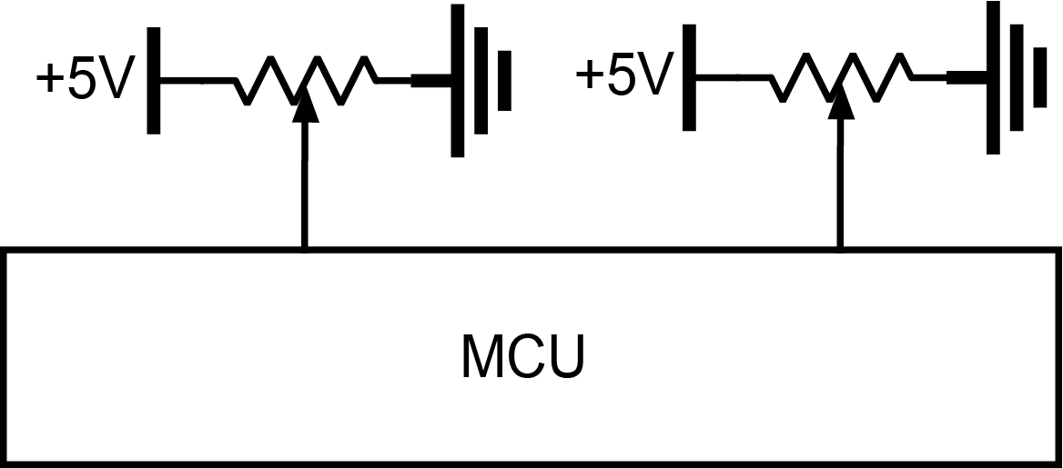
I connected the potentiometer to ground, vcc, and the middle pin to analog pin 0 on the Arduino. I then read the input, mapped the input range (0-1023) to 0-180. I controlled the servo with the servo library.
Code
#include <Servo.h>
Servo servo; //create instance of Servo
int angle;
int potPin = 0;
void setup()
{
servo.attach(9); //initialize on pin 9
Serial.begin(9600);
}
void loop() {
angle = map(analogRead(potPin),0,1023,0,180);
Serial.println(angle);
servo.write(angle);
delay(20);
}
Demo
Part 2: DC Motor Control
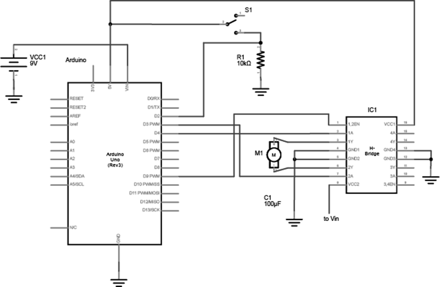
I used and H bridge IC in this circuit to allow the motor to rotate in both directions, toggled by a switch. The code just reads the switch and outputs to two digital outputs.
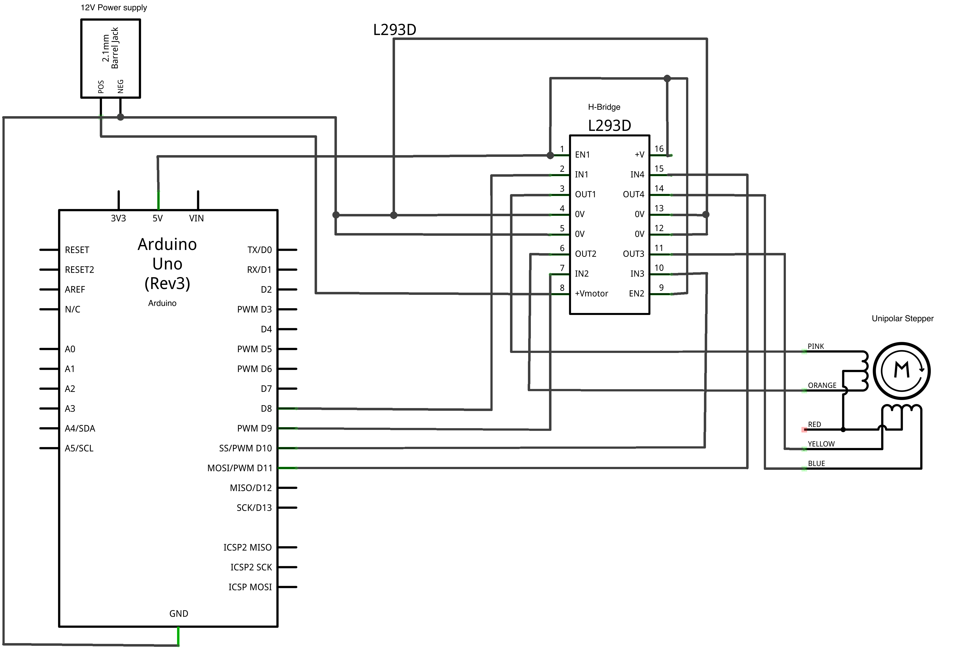
I used the stepper library to drive the H-bridge and subsequently the stepper motor. Here's the circuit:
Code
#include <Stepper.h>
const int stepsPerRevolution = 48;
// initialize the stepper library on pins 0 through 3
Stepper stepper(stepsPerRevolution, 0, 1, 2, 3);
void setup() {
// set the speed at 30 rpm:
stepper.setSpeed(30);
}
void loop() {
stepper.step(stepsPerRevolution);
delay(500);
}
Demo
Project 2 Proposal
Overview
For project 2 I'm going to make an interactive grid of LEDs. You can use a finger to draw in different colors and erase.
Technical Details
The grid itself will be a 16x16 array of RGB LEDs, specifically addressable WS2812B LEDs. For detecting finger movement, I'll have infrared emitter and detector diodes along the top and side, 16 for each. That way when a finger is placed over the grid, one set of sensors will determine the column and the other will determine the row, which can be used to find the 2D position of the finger. I'll put them in a housing so they only shine and detect directly in front of them and don't interfere with each other. I'll have a set of 3 linear potentiometers to set the color, one for red, one for green, and one for blue, and when they're all at zero it will act as an eraser. I'll have a regular RGB LED next to the color selectors to preview what the color looks like, which will take 3 pwm pins. I'll need 1 pin to output to the grid, 3 analog in pins to get input from the color sliders, 1 pin for a reset button to clear the display, and I'll use a 32 to 1 analog multiplexer to read from the 32 IR detectors into 1 analog pin using 5 pins to select. All told, I'll need 3+1+3+1+1+5=14 pins, with 3 being pwm and 4 being analog inputs, which any standard Arduino is capable of. Lastly I'll need a 5V power supply capable of supplying 75 watts to power all the lights.
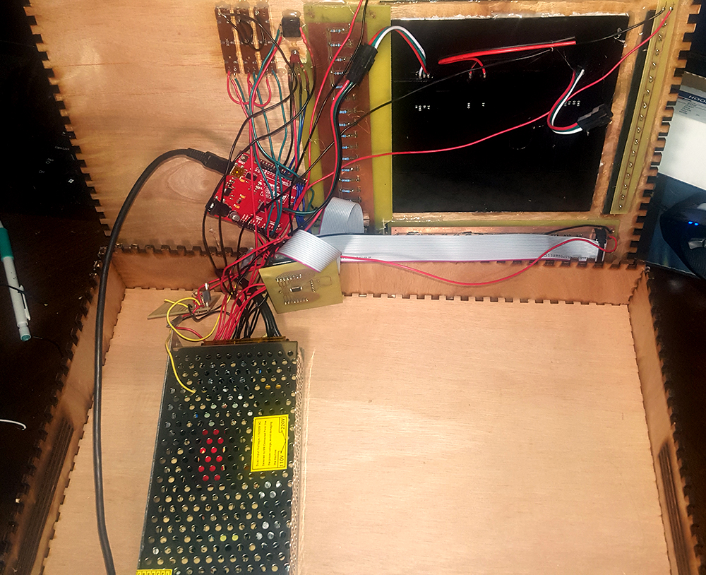
Fabrication
I'm going to use the Micro because it's small and already comes with through hole connectors. I'll make the enclosure a wood box. The LED grid and circuitry will sit inside the box, and the top will have holes for all the lights, the sliders, the reset button, the color preview, and the IR emitters and detectors. I'll then have risers on the 4 sides to house the IR beam emitters and detectors. I'll have a fan and vents in the side of the casing to prevent the 75 watts of LEDs from overheating.
In P5 I made a ball that bounces around. Two potentiometers connected to the Arduino control the gravity in the x and y direction. The color of the ball changes based on how fast it is moving. Circuit:
I made a MIDI controller that you can play like a wind instrument. An Arduino Micro reads input from the 12 buttons and reads analog values from a microphone in the mouthpiece, and then it uses MIDI to communicate with a host computer via the Arduino's native USB port. The bulk of the work for communicating with a pc is done with the MIDIUSB library.
Video demonstration:
A Bit of Music Theory
This whole project relies on an understanding of how music works, so to start I'll define a couple terms that I'll be using later. A note is a tone at a specific frequency, and notes are represented by the letters A-G. A C scale consists of the notes C D E F G A B C. The Cs at the ends of the scale are one octave apart. In general, notes are grouped into octaves, and the octave can be included as a number after the note name, so the same scale could be extended over multiple octaves like this: C4 D4 E4 F4 G4 A4 B4 C5 D5 E5 F5 G5 A5 B5 C6. Each octave consists of 12 semitones, called a chromatic scale. This scale includes notes that are halfway between the named notes using sharps (denoted by #) that raise the note by a half step and flats (b) that lower the note by a half step. All the notes in an octave are as follows: C C# D D# E F F# G G# A A# B C. C# and Db are the same note, since C and D are one step apart, so going down a half step from D and up a half step from C ends up in the same place. There is no half step between E and F or B and C, not for any particular reason, that's just the way the scale is. To illustrate what these terms are, you can listen to the audio below.
Octaves:
Chromatic Scale:
C Scale:
The MIDI Specification
MIDI (Musical Instrument Digital Interface) is the standard for digital devices communicating musical information to each other. What information exactly? The two messages I am concerned with are note on and note off. Note on and note off are both 3 byte commands that look like ssssnnnn 0kkkkkkk 0vvvvvvv. The first 4 bits (ssss) specify what type of message is being sent, 1000 is note off and 1001 is note on. The next 4 bits (nnnn) are the channel number. MIDI has 16 different channels (0-15) so different MIDI devices don't interfere with each other. 0kkkkkkk is what note is being played. The values go from 0-127 (C-1 to G9), with middle C (C4) being 60, C#4 being 61, and so on up the chromatic scale. 0vvvvvvv is the velocity, or how loud the note should be played, which again goes from 0-127. For example, if I wanted to play middle c on channel 15 with 64 velocity, the message would look like 10011111 00111100 01000000. To stop the note, the message would be 10001111 00111100 00000000. In the note off message, the velocity doesn't matter, since it is just stopping a note that has already been triggered.
Synthesizers
While MIDI says what notes to play and when, it says nothing about how to actually create sound. This requires a synthesizer. Synthesizers exist as standalone pieces of equipment or as software on a computer. They generate sound using oscillators, or devices that can create a waveform of varying shapes and frequencies. The gritty details of audio synthesis are beyond the scope of this post, but there is plenty of information online for a more complete picture. Suffice it to say a synthesizer recieves MIDI input, triggers the oscillators to play at whatever frequency is specified by the note number, and then outputs the audio to speakers. In this case, I am using Ableton Live as the host program. It can accept MIDI input and has a ton of built in synthesizer sounds to choose from.
Building the Enclosure
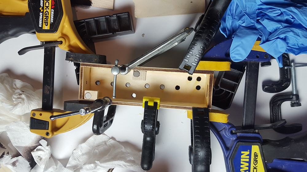
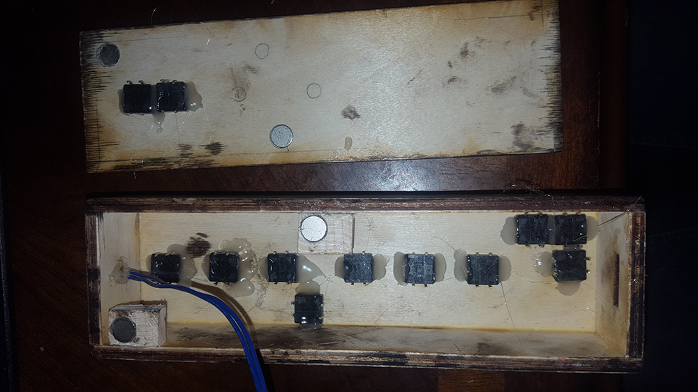
I built the enclosure from laser cut wood, with holes for 12 buttons, 10 in the front and two in the back. I play flute, so this layout mimics the keys on a flute. I started with this design, which also has holes for the microphone in the top and the usb port on the bottom.
Assembling it required some clamping and gluing. I also added some magnets on the inside and outside of the case so I could remove the back.
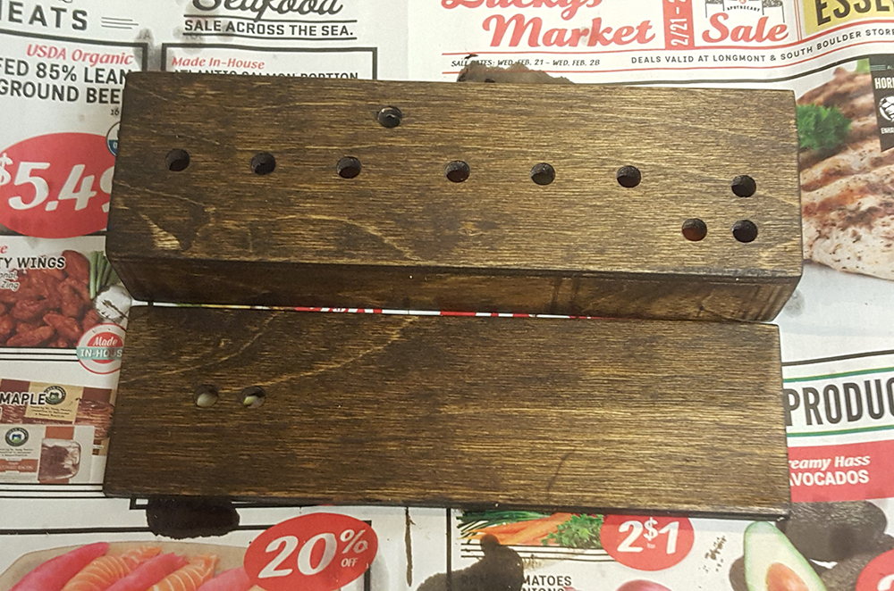
I applied a coat of stain and a coat of varnish to make it look nice, and then I drilled holes around the microphone to allow air flow.
I hot glued in all the buttons and the microphone on top.
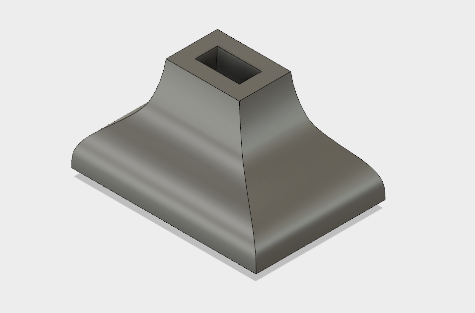
I modeled the mouthpiece in Autodesk Fusion 360, 3D printed it, and attached it to the body with hot glue.
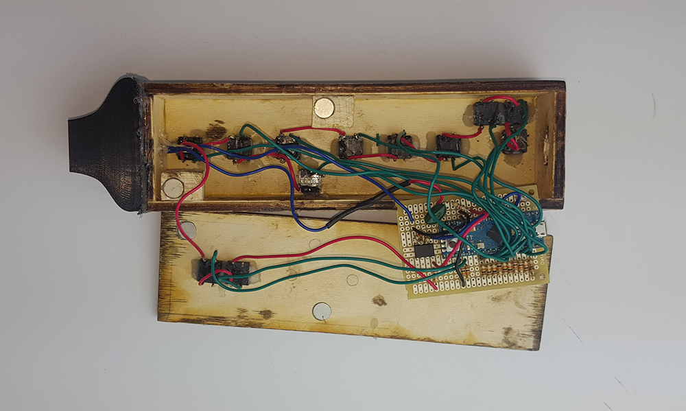
Finally, I soldered everything together as shown in this diagram. The microphone only outputs less than a volt, so I used an op amp to amplify the signal prior to going into the Arduino.
The finished product:
The Code
#include <MIDIUSB.h>
//operating on channel 15
unsigned int micPin = 0; //microphone input pin
unsigned int prevNote = 0; //variable for storing previously active note
unsigned int activeNote = 0; //variable for current note to be played
unsigned int oct1Cutoff = 30; //microphone cutoff for octave 1
unsigned int oct2Cutoff = 400; //cutoff for octave 2
unsigned int buttonInput; //stores input from buttons in bit array
unsigned int micVal; //stores analog value from reading microphone
void noteOn(byte pitch, byte velocity) { //functions for sending note on and note off packets to computer, provided by MIDIUSB Library
midiEventPacket_t noteOn = {0x09, 0x9F, pitch, velocity};
MidiUSB.sendMIDI(noteOn);
}
void noteOff(byte pitch, byte velocity) {
midiEventPacket_t noteOff = {0x08, 0x8F, pitch, velocity};
MidiUSB.sendMIDI(noteOff);
}
unsigned int getInput(){ //get which buttons are pressed, reads multiple times for debounce and stores in bit array
unsigned int bitarr = 0;
for(int j=0; j<5; j++){ //take 5 reads of each button
for(int i=0; i<12; i++){ //read digital input pins 0-11
//Serial.print(i);
//Serial.print(" ");
//Serial.print(tmp);
bitarr |= digitalRead(i)<tmp2){
tmp2 = tmp;
}
}
return tmp2;
}
void setup() {
Serial.begin(115200);
pinMode(0,INPUT);
pinMode(1,INPUT);
pinMode(2,INPUT);
pinMode(3,INPUT);
pinMode(4,INPUT);
pinMode(5,INPUT);
pinMode(6,INPUT);
pinMode(7,INPUT);
pinMode(8,INPUT);
pinMode(9,INPUT);
pinMode(10,INPUT);
pinMode(11,INPUT);
}
void loop() {
buttonInput = getInput(); //read buttons
micVal = (getMic()+micVal)/2; //read microphone and average it with the last value for smoothing
if(micVal>oct1Cutoff){ //if the microphone reads over the cutoff for octave 1, play 1st octave note
switch(buttonInput){ //each combination of buttons has its own unique integer, flute has multiple
//redundant fingerings for each note. Switch statement assigns MIDI note value for each valid fingering
case 2525: //low c fingering, value 60
case 2526:
activeNote = 60;
break;
case 1501: //c#
case 1502:
activeNote = 61;
break;
case 477: //d
case 478:
activeNote = 62;
break;
case 989: //d#
case 990:
activeNote = 63;
break;
case 733: //e
case 734:
case 221:
case 222:
activeNote = 64;
break;
case 93: //f
case 94:
case 605:
case 606:
activeNote = 65;
break;
case 157: //f#
case 158:
case 285:
case 286:
case 669:
case 670:
case 797:
case 798:
activeNote = 66;
break;
case 29: //g
case 30:
case 541:
case 542:
activeNote = 67;
break;
case 61: //g#
case 62:
case 573:
case 574:
activeNote = 68;
break;
case 13: //a
case 14:
case 525:
case 526:
activeNote = 69;
break;
case 5: //a#
case 70:
case 517:
case 582:
case 69:
case 581:
activeNote = 70;
break;
case 6: //b
case 518:
activeNote = 71;
break;
case 4: //high c fingering
case 516:
activeNote = 72;
break;
case 0: //high c# fingering
case 512:
activeNote = 73;
break;
default :
activeNote = 0;
}
}
else{ //if the mic value is too low, play nothing
activeNote = 0;
}
if(micVal>oct2Cutoff){ //if the mic is above the octave 2 cutoff, add 12 semitones to raise
if(activeNote != 0){ //the pitch by one octave if the fingering is from the 1st octave
activeNote += 12;
}
else{ //the fingerings for the upper octave of flute are different from the first 2 octaves,
switch(buttonInput){ //so if the fingering isn't from the lower octave, check if it is an upper octave fingering
case 25: //upper register d
case 26:
case 537:
case 538:
activeNote = 86;
break;
case 1021: //d#
case 1022:
activeNote = 87;
break;
case 717: //e
case 718:
activeNote = 88;
break;
case 597: //f
case 598:
activeNote = 89;
break;
case 789: //f#
case 790:
activeNote = 90;
break;
case 28: //g
case 540:
activeNote = 91;
break;
case 60: //g#
case 572:
activeNote = 92;
break;
case 585: //a
case 586:
activeNote = 93;
break;
default :
activeNote = 0;
}
}
}
if((prevNote != activeNote)){ //only send a message if the note being played has changed
if(prevNote != 0){ //if another note was on previously, send an off message to turn off that note
noteOff(prevNote,0x7f);
}
if(activeNote != 0){ //if a new note is being played, send a note on message with max velocity
noteOn(activeNote,0x7f);
}
MidiUSB.flush(); //send queued messages
}
prevNote = activeNote; //whatever note was just played is now the previous note
//Serial.print(buttonInput);
//Serial.print(" ");
//Serial.print(micVal);
//Serial.print(" ");
//Serial.println(activeNote);
}
The MIDIUSB library handles sending the MIDI messages to the computer, and the functions noteOn and noteOff were provided in the documentation for the library, so all I had to do was set up the individual bytes of information to be sent out. The principle behind reading the button input is that each button will read a 0 or 1, and if it reads 1 then the 1 is shifted over by the number of its pin. The thumb buttons go into pins 0 and 1, so they are shifted over by 0 places and 1 place respectively. If you just pressed the thumb button going into pin 0, the integer buttonInput would be 1. Pressing the button going into pin 1 would set buttonInput to 2, and pressing both would set buttonInput to 3. To finger low C, you have to press the buttons going into pins 0,2,3,4,6,7,8, and 11. Using a logical OR effectively adds those powers of two together (1<<0 | 1<<2 etc) to get 1+4+8+16+64+128+256+2048=2525, which we see in the switch statement is the value associated with note value 60, or middle C. 2026 is equivalent since it is the same fingering except it uses the other thumb key. Flute is full of alternate fingerings for different purposes, which is why there are multiple values in the switch statement for each note. The getMic function reads the microphone pin 100 times and returns the highest reading, and this is what is used to control what octave is played.
Conclusion
I feel that the project was sucessful, since it is functional. The biggest problem is blowing into a microphone isn't a very accurate measure of airflow, which is why in the video the tone tends to jump around a lot. I think the best way to fix this would be to use a different mechanism entirely to measure the airflow. I have an idea for a mechanical solution that I'll document fully if I get around to making a mk 2. I also didn't like the buttons very much, since they required a substantial amount of force to depress fully, and that isn't ideal for emulating an instrument where you need to press buttons very quickly and precisely. That's an easy fix though, I just need to find some better buttons.
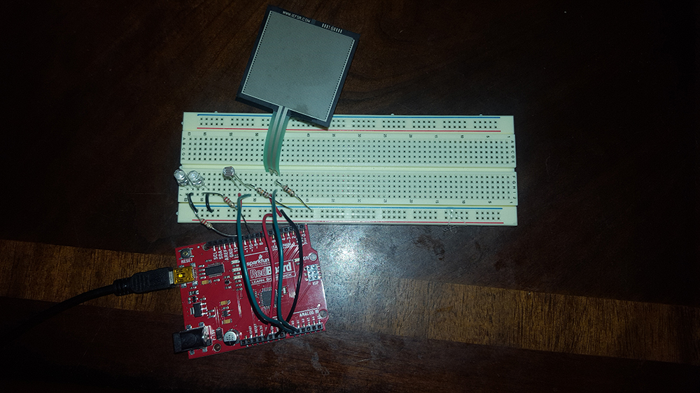
For lab 3 I had to build 3 circuits utilizing analog sensors: one that was a simple LED dimmer controlled by a potentiometer, one that was two dimmers controlled by a photoresistor and a pressure sensor, and one that would output a tone based on two photoresistors acting as a voltage divider.
Circuit 1
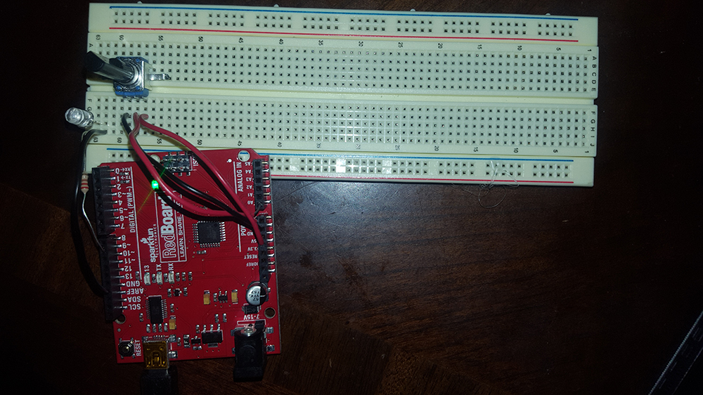
LED that is dimmed using PWM controlled by a potentiometer.
Schematic:
Code:
int ledpin = 9; //pin for the LED
int ledval; //LED brightness
int potpin = 0; //potentiometer pin
int potval; //potentiometer value
void setup() {
pinMode(ledpin,OUTPUT);
Serial.begin(9600);
}
void loop() {
potval = analogRead(potpin); //read potentiometer
ledval = potval/4; //convert 0-1023 to 0-255
analogWrite(ledpin, ledval); //write pwm to LED
Serial.println(ledval); //report brighness to PC
delay(50);
}
Circuit:
Video:
Circuit 2
Two LEDs that are dimmed using PWM controlled by a photoresistor and a pressure sensor (R3 and R4).
Schematic:
Code:
int ledpin = 9; //pin for the LED
int photopin = 0; //photoresistor pin
int pressurepin = 1; //pressure sensor pin
int photoval; //value from photoresistor
int pressureval; //value from pressure sensor
int rled = 10; //Red LED pin
int gled = 9; //Green LED pin
void setup() {
pinMode(rled, OUTPUT);
pinMode(gled, OUTPUT);
Serial.begin(9600);
}
void loop() {
photoval = analogRead(photopin); //read sensors
pressureval = analogRead(pressurepin);
int rledbrightness = map(photoval, 30, 700, 0, 255); //adjust photoresistor range
int gledbrightness = pressureval/4; //adjust pressure sensor reading
analogWrite(rled, rledbrightness); //write to LEDs
analogWrite(gled, gledbrightness);
Serial.print("Photo: "); //output sensor values to serial
Serial.print(photoval);
Serial.print(" Pressure: ");
Serial.println(pressureval);
delay(10);
}
Circuit:
Video:
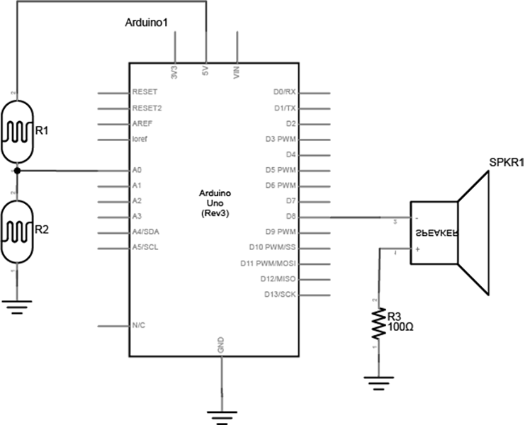
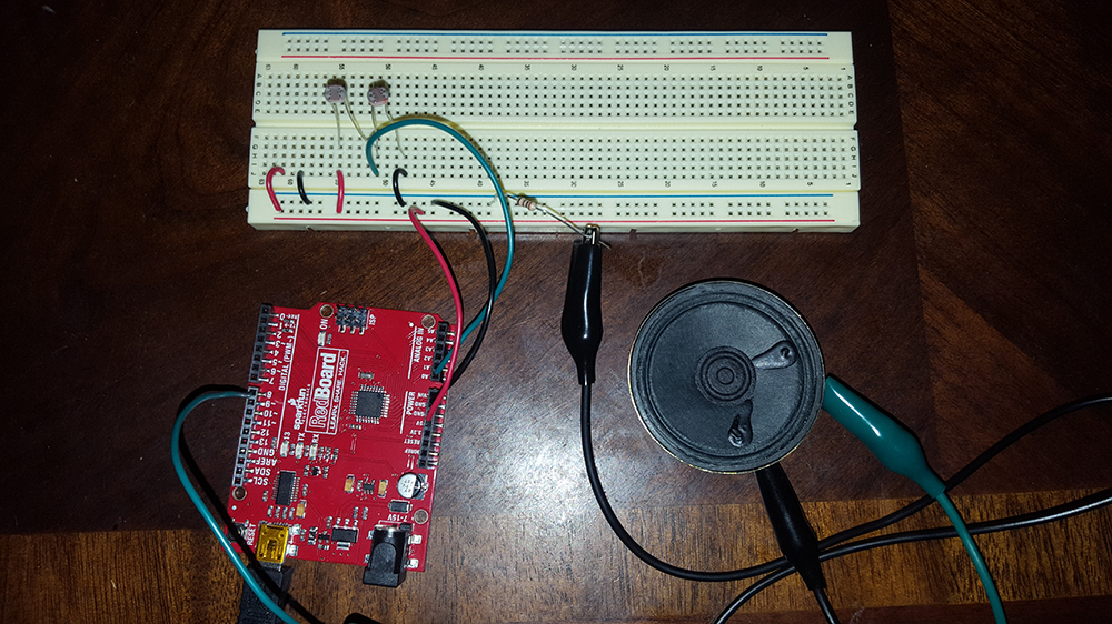
Circuit 3
Two photoresistors act as a voltage divider to control a tone output to a speaker. Rather than directly mapping the input voltage to frequency, the output will only play the notes in a major triad over several octaves. See the video if that doesn't make sense.
Schematic:
Code:
int photopin = 0; //photoresistor pin
int photoval; //photoresistor value
int index; //value for indexing interval array
int octave; //output octave
int frequency; //output frequency
int speakerpin = 8; //speaker pin
double intervals[] = {1, 1.2599, 1.4983}; //ratio of 1st, 3rd, and 5th scale degrees to root frequency for playing arpeggio
double root = 130.81; //root note, in this case C3
void setup() {
Serial.begin(9600);
}
void loop() {
photoval = analogRead(photopin); //read photoresistor
index = map(photoval, 30, 850, 0, 12); //map range of photoresistors to 12 notes (4 octaves)
if(index>12) { //cap index at 12
index = 12;
}
octave = index/3; //every 3rd note is the start of a new octave
index = index % 3; //used to determine whether note is 1st, 3rd or 5th within each octave
frequency = root * (1<
Circuit:
Video:
Project 2 Proposal
Overview
I am going to build an electric wind instrument MIDI controller. This project is primarily for me, since I play saxophone and flute and it would be cool to have a MIDI controller that I can play like a flute. The fingering patterns will be similar to flute (fingering chart here).
What is MIDI?
MIDI is a protocol for transmitting musical information. As opposed to an audio cable, which is used to send an analog waveform, MIDI digitally communicates what notes are being played, how loud they are, how they change over time, and when they stop being played. If you're interested, you can find the full specifications here. By themselves, these messages only say what notes to play, so MIDI is like a digital form of sheet music. Sheet music requires a musician to perform it in order to be heard, and MIDI requires something called a synthesizer to actually make sound. The synthesizer takes the MIDI messages and then translates this information into an audio signal at the correct pitch and intensity. Within the scope of this project, I will be using an Arduino to read button presses, convert this to MIDI messages, and then transmit those messages to a host program on a computer. In this case Ableton will be the synthesizer.
How It Will Work
I'll need a switch for each key, around 12 in total. An electret microphone will read how hard the user is blowing, and then I'll amplify it with an op-amp, since the microphone itself only outputs a few millivolts. The total range of volume from the microphone will be split into three sections to determine what octave to play (e.g. for 5V range, 0-1.6V = 1st octave, 1.6-3.3V = 2nd octave, 3.3-5V = 3rd octave), and within each octave the volume will send a control signal that I can use to add vibrato or change the timbre of the sound.
Fabrication
The body will be a wood box made out of 1/4" plywood that will be approximately 2.5" wide, 2" tall, and 10" long with rounded corners. The buttons are 14mm (0.55") tall, so I'll drill holes through the wood and affix the buttons on the inside so that the tops are poking through. I'll also add hinges for easy access to the internals, and I'll 3d print a mouthpiece to blow into and to house the pressure sensor. An Arduino Micro will drive it, since it has a smaller form factor than the Uno with the same number of pins. The Arduino's built in USB port will interface with the computer, and there is already a MIDI USB library that is designed for exactly this purpose. I'll stain the wood so it looks nice, and I'll use black buttons and black filament for the 3d printer to complement that look. Below is a rough sketch of what the final design will look like.
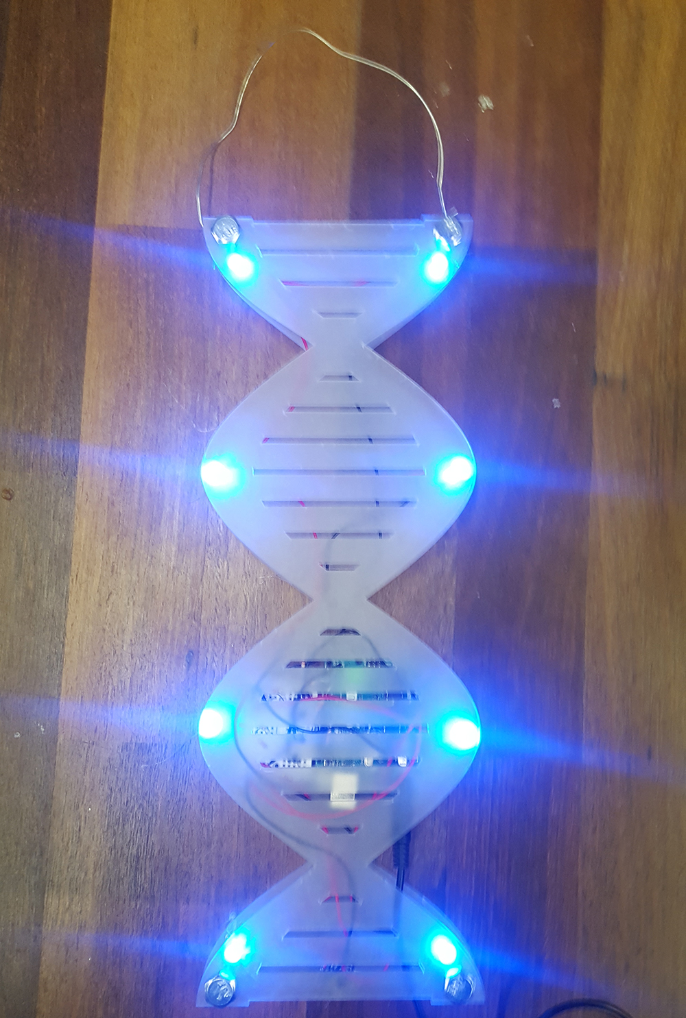
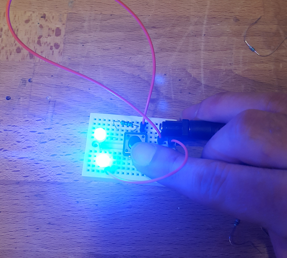
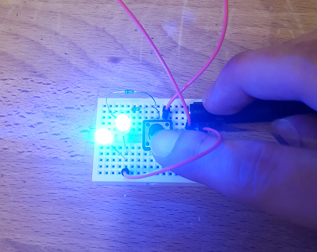
I started with the idea of laser cutting pieces to create a 3D double helix, but that quickly became way too complicated, so I instead decided to make a 2D version. I drew up a design in Illustrator, laser cut 2 faces, and used bolts, nuts, and cut up pieces of tubing as spacers to create the enclosure. I then sandwiched the electronics in the middle. There are 8 LEDs in total, 4 sets of 2 distributed along the height, and each pair is able to be activated individually. When the button is not pressed, the lights are all on continuously. When the button is pressed, it goes into rave mode and the lights rapidly sequence up and down.
Lab 1 Pt 2/3
Series Circuit:
Parallel Circuit:
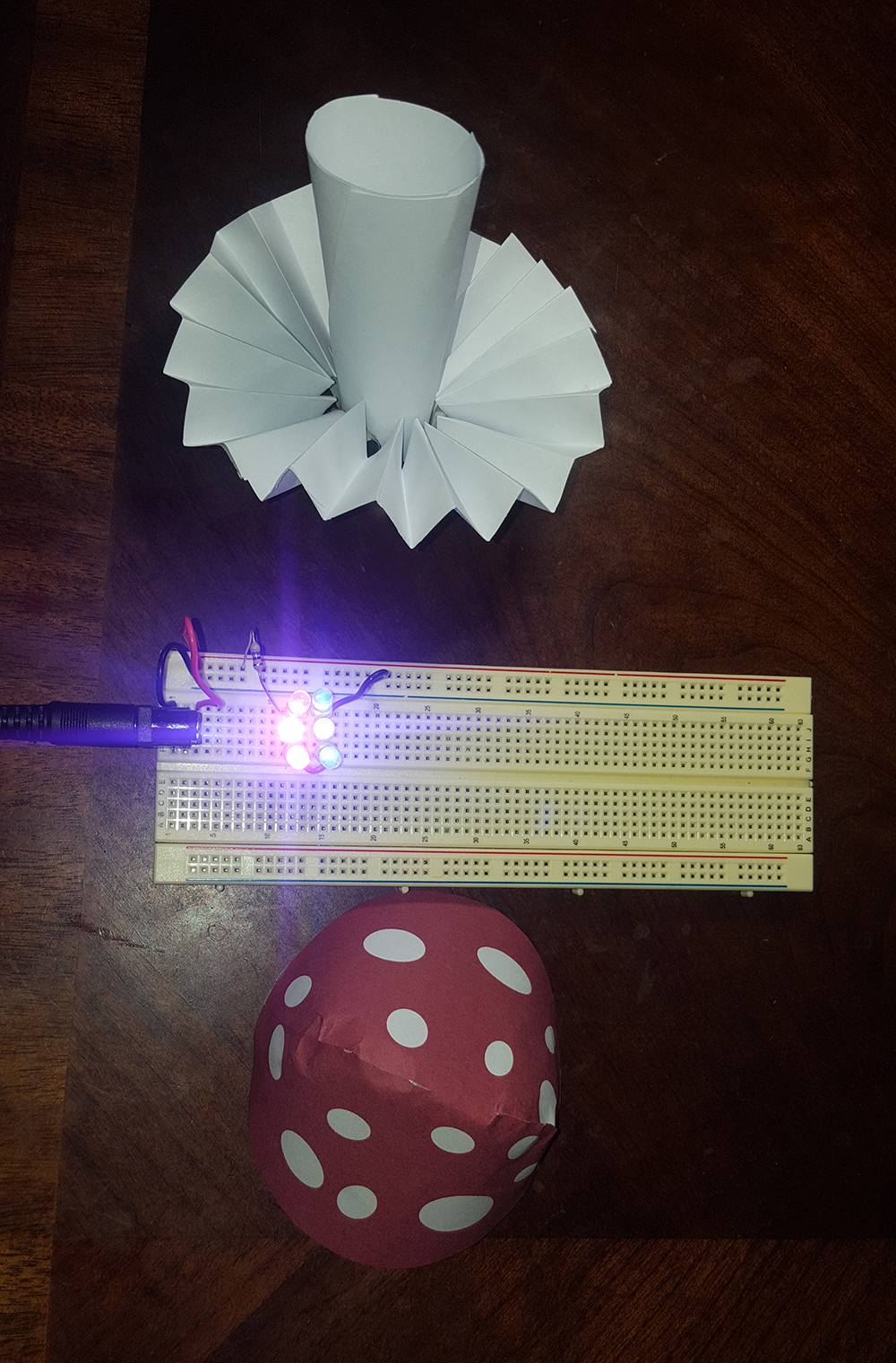
Enclosure:
The circuit is 3 parallel branches of 2 LEDs in series. For the enclosure, I tried to make a paper mushroom with lights on top. It got a little mangled in the process of assembling and trimming, but at least it's clear what it's supposed to be.
Lab 1 Paper Circuit
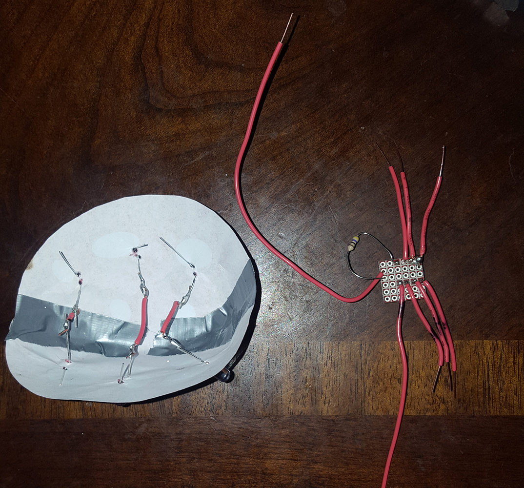
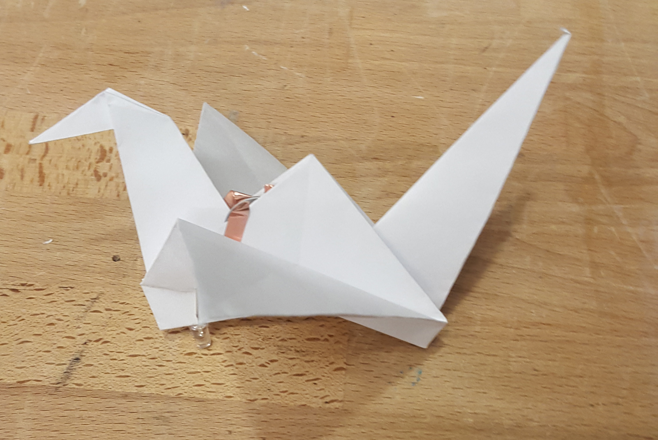
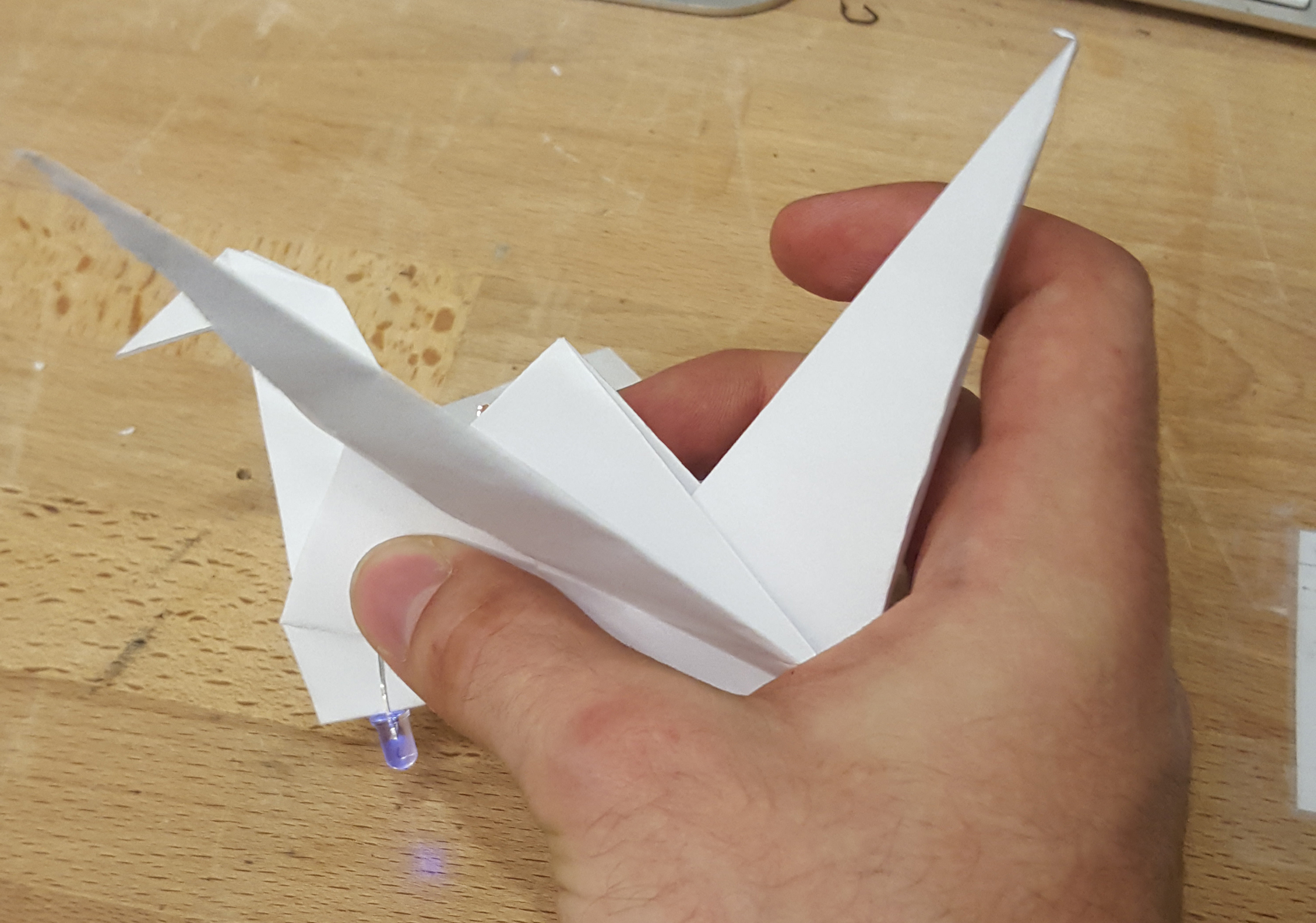
For the paper circuit, I put a landing light on a paper crane, tucked the battery into the center fold, and made it so that squeezing the front turns on the light.
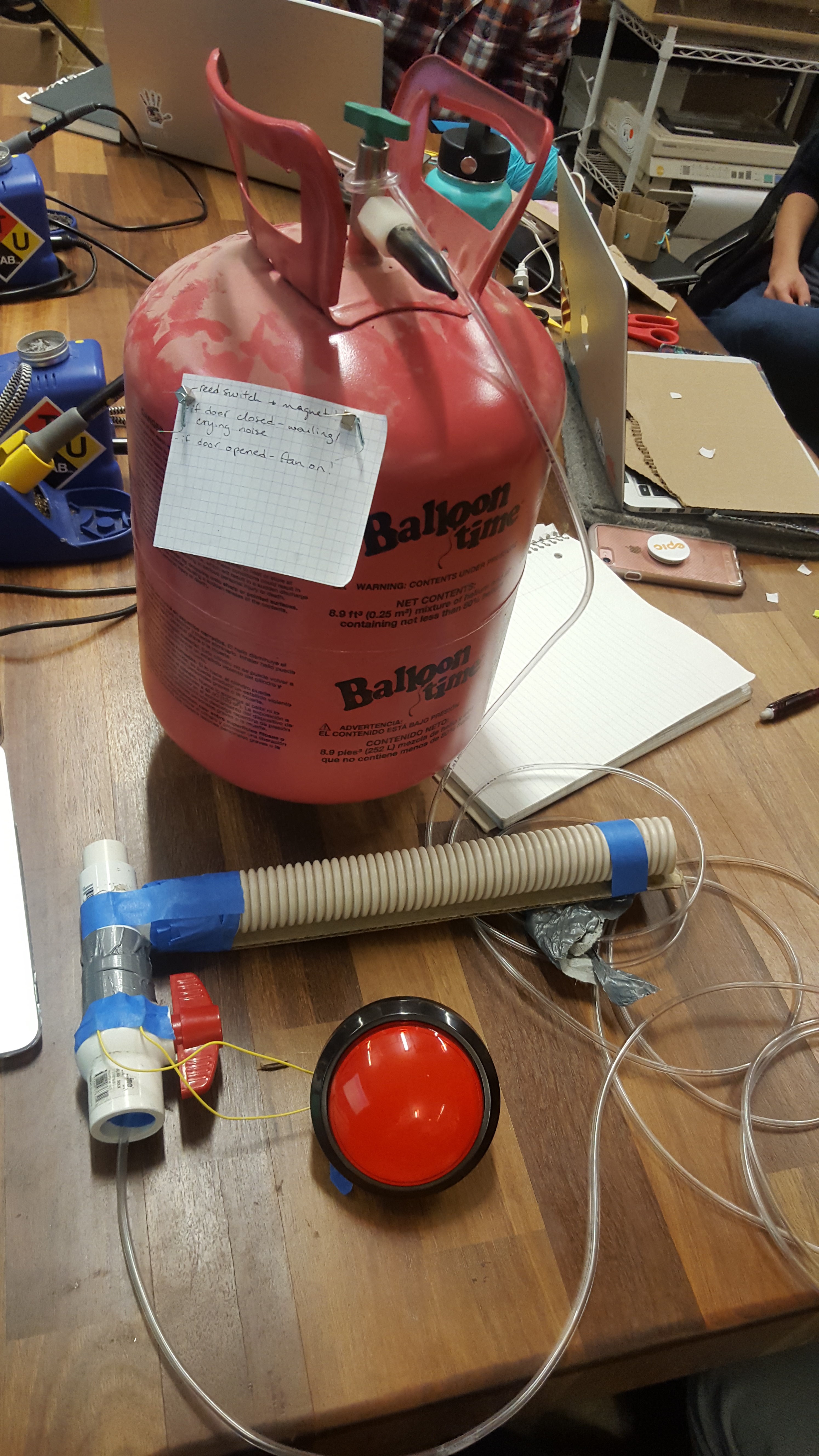
Fantasy Device
For our first day, we had to propose some sort of fantastical device and make a rough prototype using whatever we could find. Our group settled on a marshmallow cannon with automatic loading, cooking, and firing.